30
Data Logging
Data Logging
Explanation of Function
Data Logging is used to study fluctuations of system performance over a predetermined period of time. Flow,
differential pressure (∆p), temperature and power can be logged.
Connect the Dp Sensor to the valve and then perform preparations to collect system data. During the predefined
time period the Dp Sensor can be left at the site to log measurements. When the measuring period is finished the
stored data is available for downloading to the Handheld.
A logging can be performed both from a valve defined in a Hydronic Network or a separate valve free of choice.
Start a New Logging
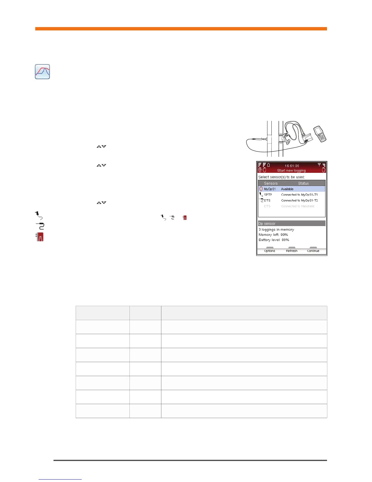
1 Connect measuring equipment according to the logging to be performed.
For e.g., Flow and temperature logging the Dp Sensor and one
temperature sensor is required. Connection details on page 15.
2 Navigate
to Data Logging in the main menu, press enter.
3 Select Start New Logging, press enter.
4 Navigate
to the type of measuring to be performed e.g., Flow and temp
logging, press enter.
5 Available sensors, their status and connections are displayed in a list. Additional
details and guidance are displayed below the list. Items not used in the logging
are grey and can not be selected.
6 Navigate
to required sensors and press enter to select. Repeat until all
required sensors are selected.
7 Selected state is indicated by an icon,
, or in front of the sensors name
in the list.
8 Press function key Continue to move on to valve settings.
9 When logging flow, differential pressure (∆p) or power, calibration is required.
10 After the calibration cycle is done enter valve and fluid preferences for the valve
to be logged.
11 If the logging is started from Hydronic Network function, see page 23, the network row is active and the circuit
name displayed.
12 If the valve is not linked to a hydronic network the network row will state Undefined.
Logging Options
Type Abbreviation Required sensors
Flow logging q DpS-Visio
Dp logging Dp (∆p) DpS-Visio
Temperature logging T 1 SPTP or 1 DTS
connected to DpS-Visio
DT logging DT (∆T) 1 SPTP + 1 DTS (or 2 DTS)
connected to DpS-Visio
Power logging P DpS-Visio & 1 SPTP + 1 DTS or DpS-Visio & 2 DTS
Flow and temp. logging q, T DpS-Visio & 1 SPTP or DpS-Visio & 1 DTS
Dp and temp. logging Dp (∆p), T DpS-Visio & 1 SPTP or DpS-Visio & 1 DTS