10 The selected module appears on the display. A blue circle with an arrow indicates that the reference valve (the last
valve) is the valve to start with. Navigate to the reference valve and press function key Measure.
11 Read the displayed instructions and connect Dp sensor nr 2 to the last valve, see page
15 for connection details. Press function key Continue.
12 After the calibration cycle is done the measurement begins and values for the last valve
are displayed in the upper right side of the screen. Adjust valve setting to the value
indicated on screen. This setting is calculated by TA-SCOPE to ensure balancing with
minimum pressure drops. You may unlock the setting by selecting Unlock valve setting
from the Options menu. Press function key Continue.
13 Read the displayed instructions and connect Dp sensor nr 1 to the “upstream”
valve. Press function key Continue.
14 The module appears on the display. The reference valve is marked with a green
tick and a blue circle with an arrow indicates that the upstream valve is the next
valve to be measured. Press function key Measure.
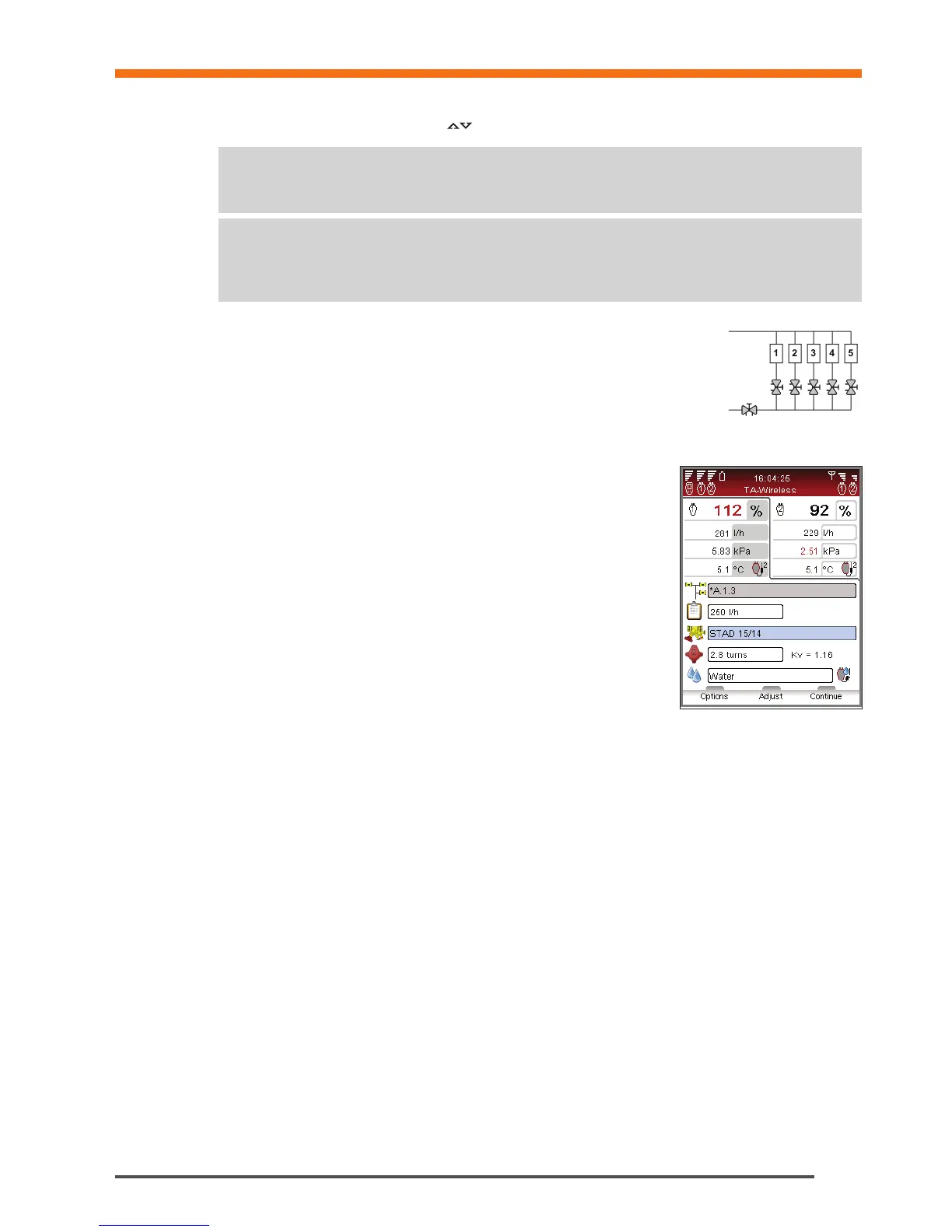
15 After the calibration cycle is done the measurement begins. Values from the two
Dp sensors are displayed side-by-side in the upper part of the screen.
16 Adjust and input valve setting until you equalize displayed flow ratios.
Alternatively you may press function key Adjust which will start a computer-
aided measuring process to equalize flow ratios. Press function key Continue
when flow ratios are equalized.
17 The module appears on the display. The reference valve and upstream valve are
marked with a green tick and a blue circle with an arrow indicates that the next
valve to be measured. Press function key Measure and repeat the process
from item 15 above.
18 Continue to measure all valves in the module until they are all marked with a green tick. Follow the sequence as
above and instructions on the display.
19 When all valves in the chosen module are measured and adjusted, an information screen is displayed with
instructions to complete the balancing of the module. Press function key Continue.
20 Leave Dp sensors 1 and 2 in place and adjust the partner valve until flow ratios of 100% are measured by both
Dp sensors. Press function key Save. The obtained flows in the first and last valves of the module are then saved
in memory.
21 To verify the completeness of the balancing process a control measurement of the other valves of the module
should be performed.
22 The collected data from the saved measurements can be uploaded to HySelect and used for a Balancing report.