21
INSTALLER
USERMAINTENANCE TECHNICIAN
TECHNICAL DATA
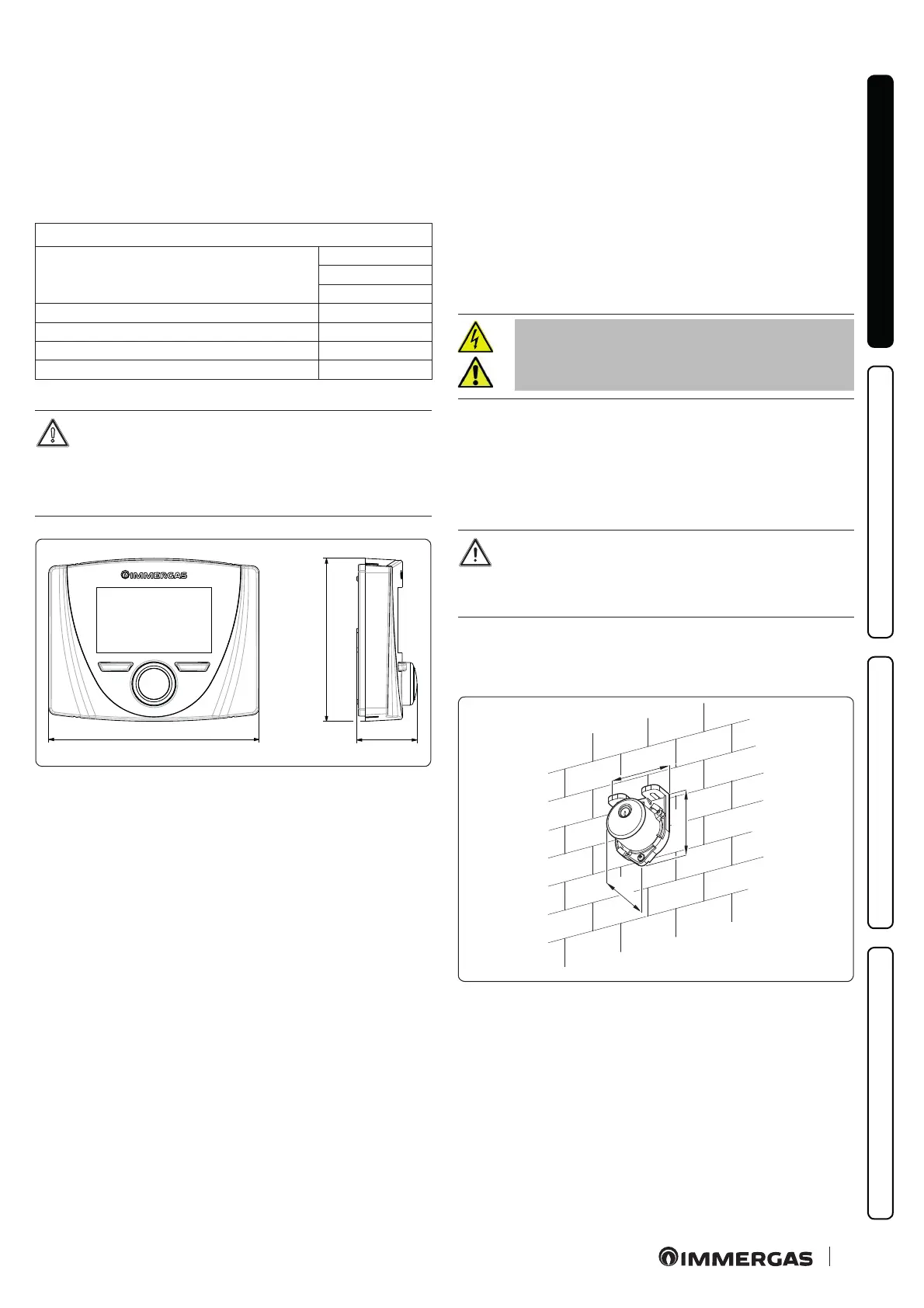
1.13 REMOTE ZONE CONTROL OPTIONAL
is remote device is used to adjust the setpoints and to view the
main information of the zone where it was congured.
Connect as shown (Fig. 11);
To correctly congure the device, set the parameters as described
below:
Assistance Menu -> Device conguration
S l a v e a d d r e s s : A d d r e s s t o c o n g u r e a c c o r d i n g t o
the zone where the device is installed
Zone 1 = 41
Zone 2 = 42
Zone 3 = 43
Baud Rate 9600
Parity bit Even
Stop bits 1
Heat pump control NO
For correct operation it is necessary to install the jumper
on the thermostat of the zone associated to the panel.
If necessary, this jumper can be replaced with a safety
thermostat.
128
99
37
12
1.14 DOMINUS OPTIONAL
e system can be remote controlled using the optional Dominus
kit.
Connect the appliance as shown (Fig. 11).
For further information, consult the relative instruction sheet.
1.15 HUMIDISTAT ON/OFF OPTIONAL
You can make a dehumidication demand by using a humidistat.
Connect as shown (Fig. 11);
1.16 EXTERNAL TEMPERATURE PROBE
OPTIONAL
In the outdoor unit there is an external probe as standard.
is can be used as an external probe of the heat pump.
If the outdoor unit is positioned in an area that is not suitable for
temperature reading, it is advisable to use an additional external
probe (Fig. 13) which is available as an optional kit.
Refer to the relative instruction sheet for positioning of the exter-
nal probe.
For the proper operation of the optional probe it must be connect-
ed where envisaged (Fig. 11) and then it must be enabled (Par-
ag. 3.13).
Once the probe is enabled, switch the ap-
pliance o and back on.
e presence of the external probe allows the system ow temper-
ature to be set automatically based on the outdoor temperature in
order to adapt the heating or cooling provided to the system.
e system ow temperature is determined by the setting on the
“Heat regulation” menu and by the “User” menu for the oset val-
ues based on the curves shown in the diagram (Parag. 1.17).
If the system is divided into two or three zones, the ow
temperature is calculated based on the zone with the
higher temperature in central heating mode and with
the lower temperature in cooling mode.
e electric connection of the external probe must be made on
terminals 38 and 39 on the terminal board on the indoor unit con-
trol panel (Fig. 11).
45
31
58
13
In case of failure, aer having powered o and back on, the out-
door temperature is automatically detected by the external probe
on the outdoor unit.

 Loading...


