39
INSTALLER
USERMAINTENANCE TECHNICIAN
TECHNICAL DATA
1.31 SYSTEM FILLING
Once the indoor unit is connected, ll the system using the lling
cock (Fig. 47).
Filling must be done slowly to allow the air bubbles in the water to
escape through the vents in the indoor unit and the heating and
air conditioning system.
e indoor unit has one incorporated automatic vent valve locat-
ed on the circulator and another on the central heating manifold.
Make sure that the hoods are loosened.
e lling cock must be closed when the indoor unit pressure
gauge indicates approximately 1.2 bar.
During these operations, enable the “Venting” func-
tions by setting the “U 50” parameter to ON, which lasts
about 18 hours (Parag. 3.13).
System minimum water content.
Minimum water content favours the proper execution of de-
frosting cycles and operation in cooling mode.
To this end, the minimum amount of water to guarantee is 30 li-
tres for any type of system and in any operating mode.
1.32 FILLING THE CONDENSATE DRAIN
TRAP
When the indoor unit is switched on for
the rst time, combustion products
c o me o ut o f t h e c o nd e n s a te d r a i n . A e r a
few minutes of operation, check that
combustion ue gases are no longer com-
ing out of the condensate drain; this
means that the drain trap has lled to a
correct condensate height that the ue
gases cannot pass through.
1.33 GAS SYSTEM STARTUP.
To start up the system, refer to the technical standards in force.
is divides the systems and, therefore, the commissioning oper-
ations, into three categories: new systems, modied systems, reac-
tivated systems.
In particular, for new gas systems:
- open windows and doors;
- avoid presence of sparks or naked ames;
- bleed all air from pipelines;
- ensure the internal system is properly sealed according to the
specications set forth by technical regulations in force.
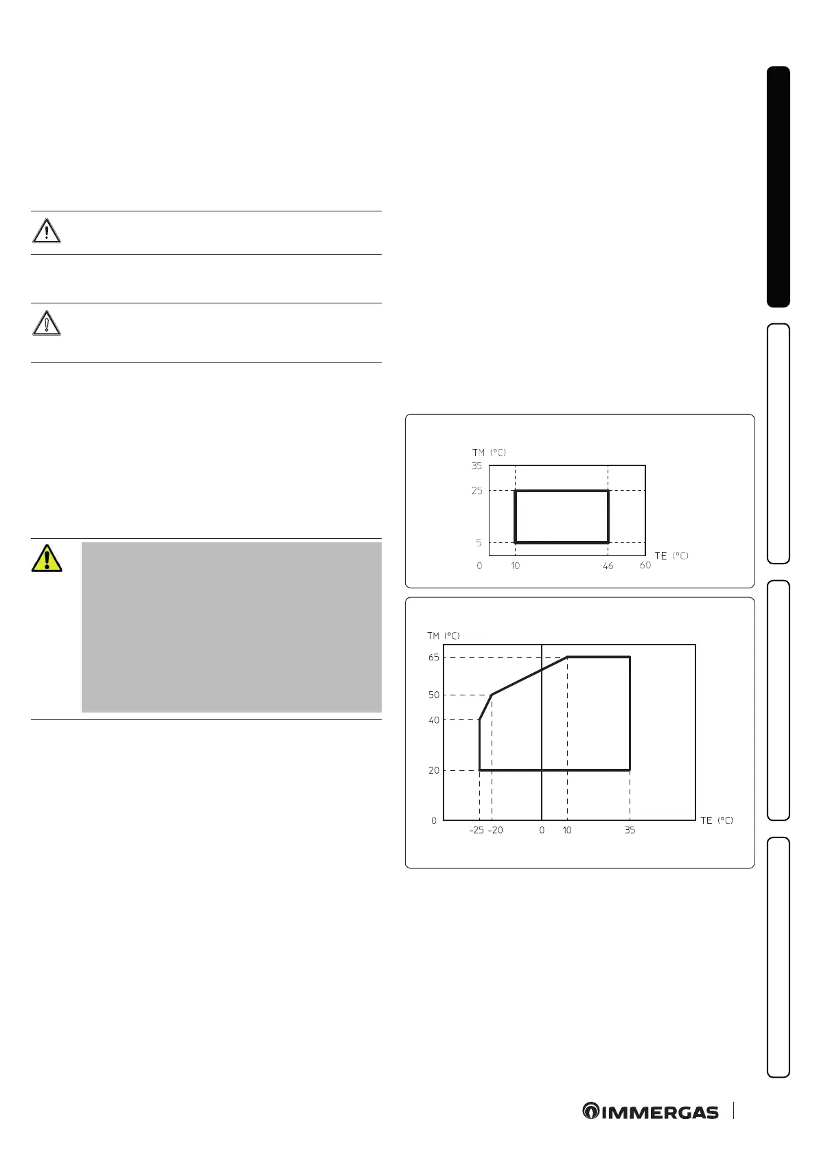
1.34 OPERATING LIMITS
e appliance was designed to work in a specic range of outdoor
temperatures and at a specic maximum ow temperature.
(Fig. 43, 44)shows these limits.
ese limit values apply to heating or cooling operation.
Domestic hot water supply is always met in any outdoor tempera-
ture conditions.
Heat pump
operating limits in cooling mode
43
Heat pump
operating limits in CH mode
44
Key (Fig. 43, 44):
TE = External temperature
TM = Flow temperature

 Loading...


