43
INSTALLER
USERMAINTENANCE TECHNICIAN
TECHNICAL DATA
1.38 MAIN COMPONENTS
1
2
3
4
6
5
7
8
9
10
12
11
14
13
15
16
17
18
19
20
21
22
23
24
25
26
27 30
31
29
28
32
36
35
34
33
38
37
33
39
47
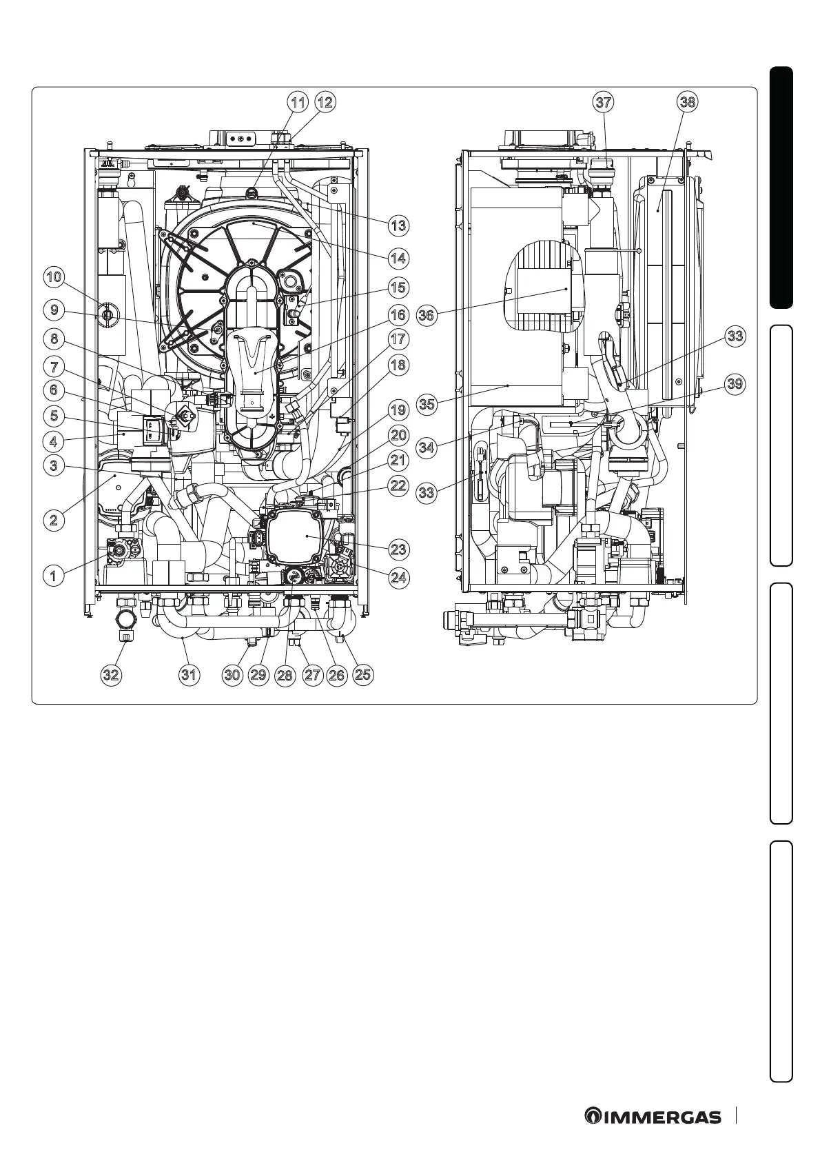
Key (Fig. 47):
1 - Gas valve
2 - Heat pump circuit circulator
3 - Condensate drain trap
4 - ree-way valve
5 - three-way valve motor
6 - DHW probe
7 - Safety thermostat
8 - Gas nozzle
9 - Detection electrode
10 - Flow switch
11 - Flue gas thermofuse
12 - Flange with sample points
13 - Heat exchanger safety thermofuse
14 - Condensation module
15 - Ignition glow plug
16 - Venturi
17 - Fan
18 - Igniter
19 - Air intake pipe
20 - One-way valve
21 - Air vent valve
22 - System pressure switch
23 - Heat generator circuit circulator
24 - Heat generator three-way valve
25 - System shut-o cock
26 - System draining tting
27 - System shut-o cock with lter
28 - 3-bar safety valve
29 - Hydraulic unit knob
30 - Domestic hot water inlet cock
31 - Bypass pipe
32 - Gas interception cock
33 - Heat pump ow probe
34 - Liquid phase detection probe
35 - Water - gas plate exchanger
36 - Burner
37 - Air vent valve
38 - System expansion vessel
39 - Heat generator return probe

 Loading...


