23
INSTALLER
USERMAINTENANCE TECHNICIAN
TECHNICAL DATA
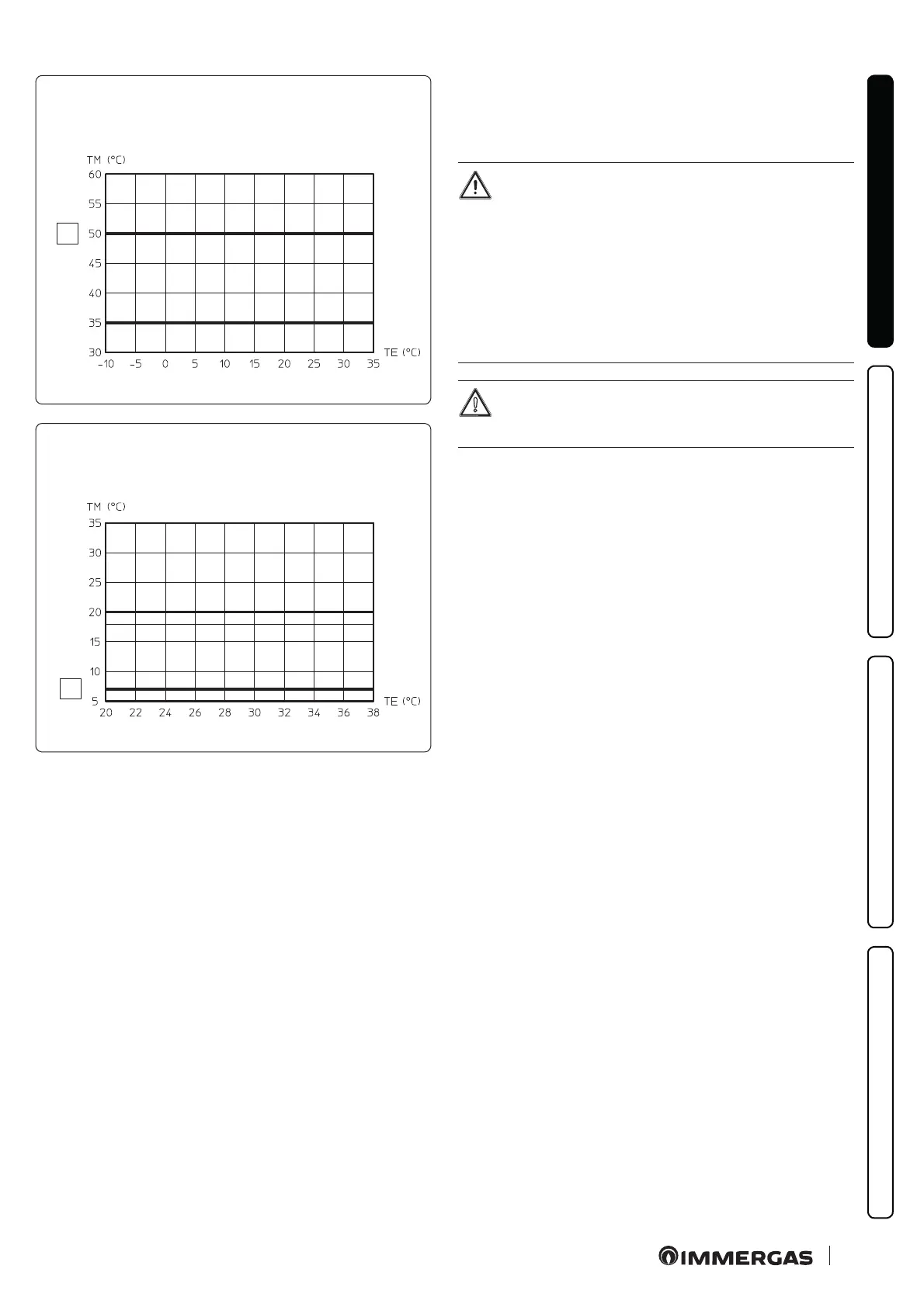
Flow temperature in central heating mode
without external probe
U01
(U14)
Z1
Z2 (Z3)
1
18
Flow temperature in cooling mode
without external probe
U02
(U15)
Z2 (Z3)
Z1
2
19
Key (Fig. 14,15,16,17,18,19)
1 - Central Heating Set
2 - Cooling Set
TE - External temperature
TM - Flow temperature
U 01 - Zone 2 ow temperature in "User" menu central heating
mode
U 02 - Zone 2 ow temperature in "User" menu cooling mode
U 14 - Zone 3 ow temperature in "User" menu central heating
mode
U 15 - Zone 3 ow temperature in "User" menu cooling mode
Zx - Heating system zone
1.18 IMMERGAS FLUE SYSTEMS
Immergas supplies various solutions separately from the indoor
units regarding the installation of air intake terminals and ue
exhaust, which are fundamental for indoor unit operation.
e indoor unit must be installed with an original Im-
mergas “Green Range” inspectionable air intake system
and ue gas extraction system made of plastic, with the
exception of conguration C
6
, as required by the regula-
tions in force and by the product’s approval. is ue can
be identied by an identication mark and special dis-
tinctive marking bearing the note "only for condensa-
tion boilers".
For non-original ue system, refer to the technical data
of the appliance.
e plastic pipes cannot be installed outdoors, for tracts
longer than 40 cm, without suitable protection from UV
rays and other atmospheric agents.
Resistance factors and equivalent lengths
Each ue component has a Resistance Factor based on experimen-
tal tests and specied in the table below.
e Resistance Factor for individual components is independent
from the type of boiler on which it is installed and has a dimen-
sionless size.
It is however, conditioned by the temperature of the uids that
pass through the pipe and therefore, varies according to applica-
tions for air intake or ue exhaust.
Each single component has a resistance corresponding to a cer-
tain length in metres of pipe of the same diameter; the so-called
equivalent length, can be obtained from the ratio between the rel-
ative Resistance Factors.
All indoor units have an experimentally obtainable maximum
Resistance Factor equal to 100.

 Loading...


