67
INSTALLER
USERMAINTENANCE TECHNICIAN
TECHNICAL DATA
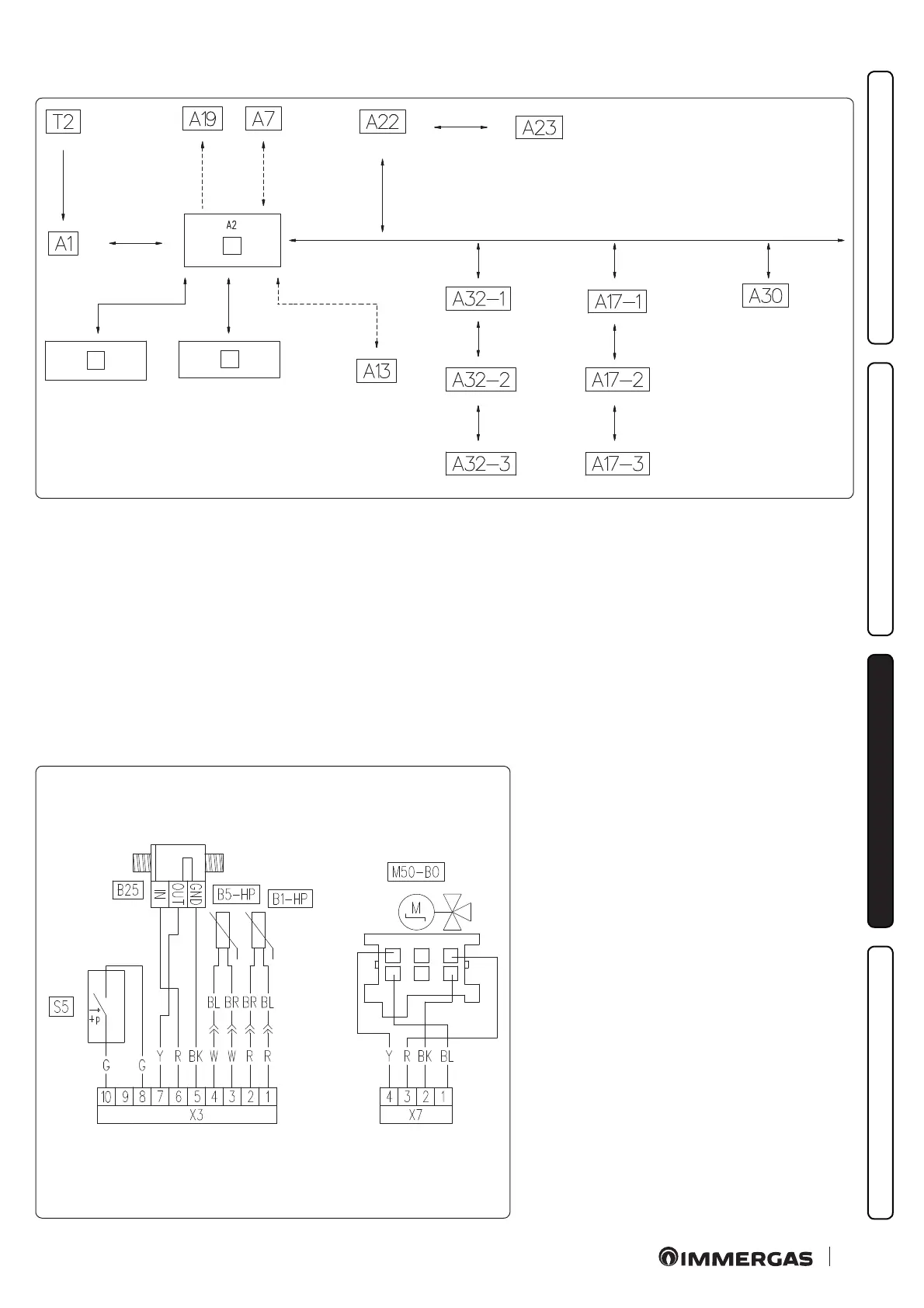
3.5 WIRING DIAGRAM
1
2
3
55
Key (Fig. 55):
1 - P.C.B.
2 - Low voltage electrical connection clamps (230 Vac)
3 - Very low safety voltage electrical connection clamps
A1 - Ignition board
A2 - P.C.B.
A7 - ree-relay board (optional)
A13 - System manager (optional)
A17-1 - Modbus zone 1 temp./humidity probe (optional)
A17-2 - Modbus zone 2 temp./humidity probe (optional)
A17-3 - Modbus zone 3 temp./humidity probe (optional)
A19 - Two-relay board (optional)
A22 - Interface board
A23 - External unit
A30 - Dominus (optional)
A32-1 - Zone 1 remote control (optional)
A32-2 - Zone 2 remote control (optional)
A32-3 - Zone 3 remote control (optional)
T2 - Ignition transformer
56
Key (Fig. 56):
A2 - P.C.B.
B1-HP - HP ow probe
B5-HP - HP return probe
B25 - System ow meter
M50-B0 - Heat unit three-way valve.
S5 - System pressure switch
Colour code key (Fig. 56):
BK - Black
BL - Blue
BR - Brown
G - Green
GY - Grey
G/Y - Yellow/Green
P - Viola
PK - Pink
R - Red
 Loading...


