76
INSTALLER
USERMAINTENANCE TECHNICIAN
TECHNICAL DATA
3.11 FAN SPEED CALIBRATION
Verication and calibration are necessary, in the case of
transformation to other types of gas, in the extraordi-
nary maintenance phase with replacement of the PCB,
air/gas circuit components or in the case of installations
with ue extraction systems, with horizontal concentric
pipe measuring more than 1 metre.
e indoor unit heat output is correlated to the length of the air
intake and ue exhaust pipes.
is decreases with the increase of pipe length.
e indoor unit leaves the factory adjusted for minimum pipe
length (1m). It is therefore necessary, especially in the case of max-
imum pipe extension, to check the ∆p gas values aer at least 5
minutes of the burner operating at nominal heat output, when the
temperatures of the intake air and exhaust ue gas have stabilised.
Adjust the nominal and minimum output in the domestic hot
water and central heating modes according to the values in the ta-
ble in the indoor unit manual using the dierential manometers
connected to the ∆p gas pressure points (Det. 9-Fig. 47).
Enter the congurations menu and regulate the following param-
eters (Parag. 3.13);
- DHW minimum no. of fan revs “S 00”;
- DHW maximum no. of fan revs “S 01”;
- delete ignition stage "S 02".
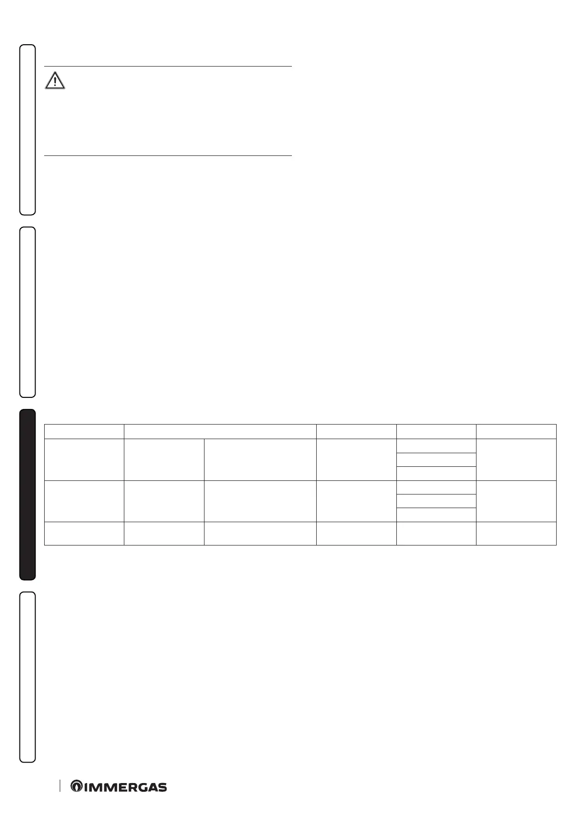
Listed below are the default settings featured:
Parameter ID Description Range Default Customised value
S 00
DHW minimum no.
of fan revs
Operating speed of the fan at
minimum DHW output
900 ÷ 1500 (RPM)
G20: 1300
G30: 1300
G31: 1300
S 01
DHW maximum no.
of fan revs
Operating speed of the fan at
maximum DHW output
3000 ÷ 6100 (RPM)
G20: 5100
G30: 4800
G31: 5400
S 02
Ignition phase fan
speed
Operating speed of the fan
during the ignition phase
0 - 100% 16
3.12 ADJUSTMENT OF THE AIRGAS RATIO
Calibration of minimum CO
2
(minimum central heating
output).
Enter the chimney sweep phase without withdrawing domestic
hot water and take the selector switches to minimum until "0" is
seen on the display.
To have an exact value of CO
2
t he tech nic ia n mu st i ns er t t he sa m-
pling probe to the bottom of the sample point, then check that the
CO
2
value is that specied in the table, otherwise adjust the screw
(Det. 3Fig. 65)(O-Set adjuster).

 Loading...


