41
INSTALLER
USERMAINTENANCE TECHNICIAN
TECHNICAL DATA
1.36 CIRCULATION PUMP
e i n d o o r u n i t i s s u pp l i e d w i t h t w o c i r c u l a t o r pu m p s , o n e fo r t h e
heat generator and another for the heat pump mode.
Circulator pumps run at variable speeds and operate as follows:
- Fixed ("A 05" = 0): e heat circulator pump speed is xed and
corresponds to parameter "A 04". e heat generator circulator
pump speed is xed and corresponds to parameter "A 19".
- ∆T constant ("A 05" = 5 K): the heat circulator pump speed var-
ies to maintain ∆T = 5 K constant between the system ow and
return. Also, you can adjust the pump operating range, by set-
ting the maximum speed “A 04” and the minimum speed “A 03”.
e h e a t g e n e r a t o r c i r c u l a t o r p u m p s p e e d v a r i e s t o m a i n t a i n ∆ T
= "A 05" constant between the system ow and return. Also, you
can adjust the pump operating range, by setting the maximum
speed “A 19” and the minimum speed “A 18”.
For proper system operation, make sure that the mini-
mum ow rate in operating conditions never drops be-
low 500 l/h.
Pump LED.
e LED ashes green when the pump is powered and the pwm
control signal is connected.
e LED lights up steady green when the pump is pow-
ered and the signal cable disconnected. In these condi-
tions the pump works at maximum and without control.
If the pump detects an alarm, the LED switches from green to red;
this can mean one of the following failures:
- low supply voltage;
- rotor seized;
- electrical error.
For a detailed description of the meaning of the red LED, refer to
(Parag. 3.13).
e LED, in addition to being green or red, can also re-
main o.
It is normal for the LED to be o when the pump is not
powered, whereas with the pump powered, the LED
must be lit: if switched o, it means there is a fault.
Pump release.
If a er a long period of i nactivit y, the ci rcu lator is blocked, adjust
the screw in the centre of the head in order to manually release the
motor sha.
Take great care during this operation to avoid damage to the mo-
tor.
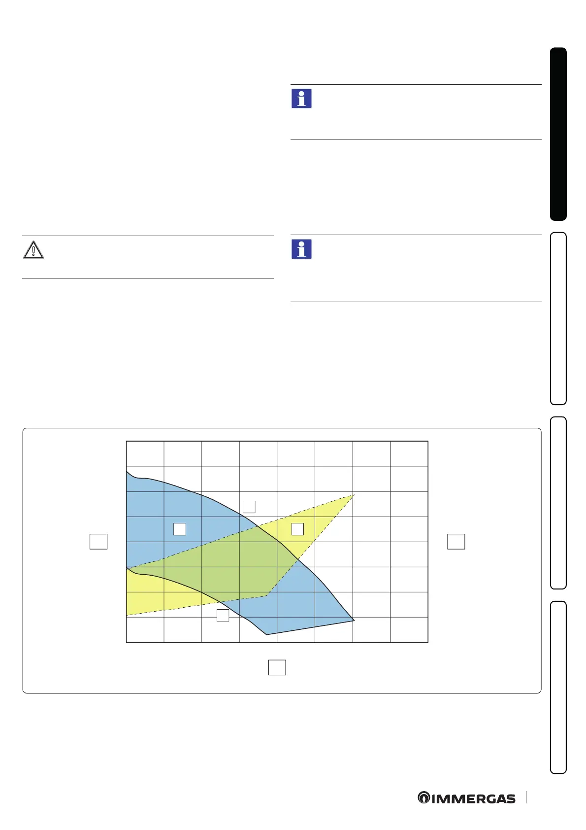
Head available to system (Heat generator circuit)
0
10
20
30
40
50
60
70
80
0
10
20
30
40
50
60
70
80
0 200 400 600 800 1000 1200 1400 1600
A
B
1
2
X1
Y1 Y2
45
Key (Fig. 45):
X1 = Flow rate (l/h)
Y1 = Head (kPa)
Y2 = Circulator pump absorbed power
(W)
1 = Maximum speed (100%)
2 = Minimum speed (70%)
A = Head available to the system
B = Power absorbed by the circulator
pump (dotted area)

 Loading...


