42
INSTALLER
USERMAINTENANCE TECHNICIAN
TECHNICAL DATA
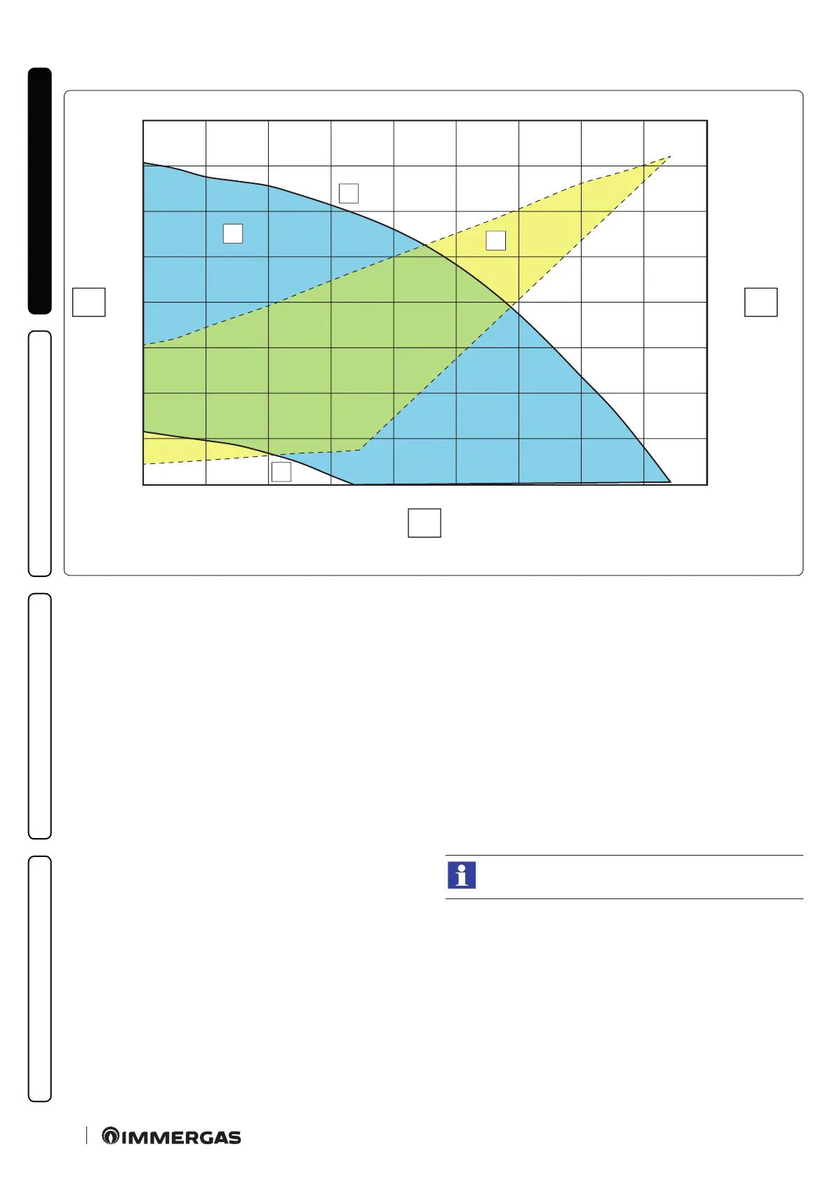
Head available to system (Heat pump circuit)
B
A
2
1
0
10
20
30
40
50
60
70
80
0 200
400
600 800 1000 1200 1400 1600
1800
0
10
20
30
40
50
60
70
80
X1
Y1 Y2
46
Key (Fig. 46):
X1 = Flow rate (l/h)
Y1 = Head (kPa)
Y2 = Circulator pump absorbed power (W)
1 = Maximum speed (100%)
2 = Minimum speed (45%)
A = Head available to the system
B = Power absorbed by the circulator pump (dotted area)
1.37 KITS AVAILABLE ON REQUEST
- 2 zone kit (1 direct and 1 mixed). Should it be necessary, you can
install the zone kit, which allows you to divide the heating sys-
tem into two separate zones - one direct and one mixed.
- Congurable relay interface kit. e module is set up for a relay
board, which amplies the appliance features and, thus, the op-
erating possibilities.
- 2-relay board kit. e indoor unit can manage up to two dehu-
midiers. A 2 relay board that manages dehumidier enabling
is available to pair the appliances.
- R32 circuit connection kit. For R32 circuit wall connections,
there is a kit with the two pipes necessary to create the circuit.
- Separate storage tank units: for DHW production, Magis Com-
bo Plus V2 can be paired with a storage tank unit (optional),
such as for example the OMNISTOR, INOXSTOR and UB
INOX ranges.
e above-mentioned kits are supplied complete with
instructions for assembly and use.
 Loading...


