11
INSTALLER
USERMAINTENANCE TECHNICIAN
TECHNICAL DATA
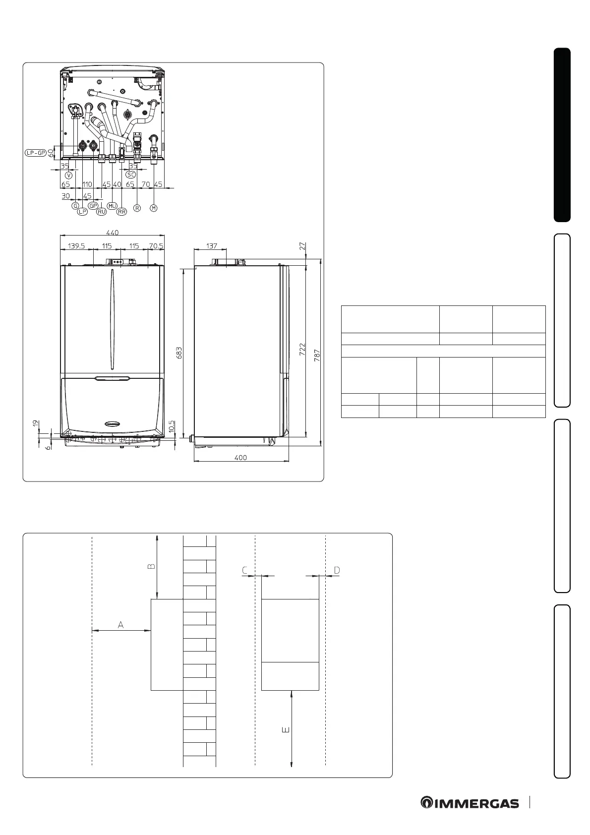
1.3 MAIN DIMENSIONS
2
Key (Fig. 2):
V - Electric connection
G - Gas supply
LP - Chiller line - liquid phase
GP - Chiller line - gaseous phase
RU - Storage tank unit return
MU - Storage tank unit ow
RR - System lling
SC - Condensate drain (minimum internal
diameter Ø 13 mm)
R - System return
M - System ow
Height
(mm)
Width
(mm)
Depth
(mm)
787 440 400
CONNECTIONS
LINE
CHILLER LINE
GAS
DOMESTIC
HOT
WATER
SYSTEM
LP GP G RR MU - RU
SAE 1/4” SAE 5/8” 3/4” 1/2” 3/4”
1.4 MINIMUM INSTALLATION DISTANCES
3
Key (Fig. 3):
A - 450 mm
B - 350 mm
C - 30 mm
D - 30 mm
E - 350 mm

 Loading...


