33
INSTALLER
USERMAINTENANCE TECHNICIAN
TECHNICAL DATA
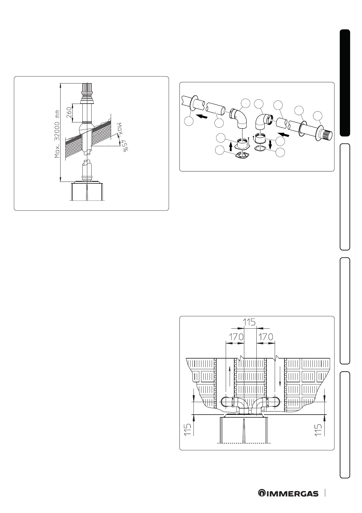
Extensions for Ø 80/125 vertical kit (Fig. 33)
e k it w it h t hi s con gu rat ion ca n b e ex te nd ed to a ma x. st ra ig ht
vertical length of 32 m, including the terminal. If additional com-
ponents are assembled, the length equivalent to the maximum al-
lowed must be subtracted. In this case the special extensions must
be requested.
C
33
33
1.24 SEPARATOR KIT INSTALLATION
Type C conguration, sealed chamber and fan assisted,
separator kit Ø 80/80
is kit allows air to come in from outside the building and the
exhaust to exit from the chimney, ue or intubated duct through
divided ue exhaust and air intake pipes.
Combustion products are expelled from pipe (S) (in plastic, so as
to resist acid condensate).
Air is taken in through duct (A) for combustion (this is also in
plastic).
e intake pipe (A) can be installed either on the right or le hand
side of the central exhaust pipe (S).
Both ducts can be routed in any direction.
Mounting the separator kit Ø 80/80 (Fig. 34):
1. Install the ange (4) on the central hole of the indoor unit, po-
sitioning gasket (1) with the circular projections downwards
in contact with the indoor unit ange.
2. Tighten with the hexagonal head and at point screws provid-
ed in the kit.
3. Replace the at ange present in the lateral hole with respect to
the central one (according to needs) with the ange (3), posi-
tioning the gasket (2) already present in the indoor unit in be-
tween.
4. Tighten with the supplied self-tapping screws with drill bit.
5. Fit the bends with male side (smooth) (5) in the female side of
the anges (3 and 4).
6. Fit the intake terminal (6) with the male side (smooth) in the
female side of the bend (5) up to the end stop, ensuring that the
internal and external wall sealing plates are tted
7. Fit the exhaust pipe (9) with the male end (smooth) to the fe-
male end of the bend (5) up to the end stop; making sure that
the internal wall sealing plate has been tted, this will ensure
sealing and joining of the elements making up the kit.
C
53
* - C
83
1
4
7
9
5
5
6
7
8
3
2
S
A
34
e kit includes (Fig. 34):
No.1 E xh au st ga sk et (1)
No.1 Flange gasket (2)
No.1 Female intake ange (3)
No.1 Female exhaust ange (4)
No.2 Bend 90° Ø 80 (5)
N o .1 I n t a k e t e r m i n a l Ø 8 0 ( 6)
No.2 Internal wall sealing plates (7)
No.1 External wall sealing plate (8)
No.1 Exhaust pipe Ø 80 (9)
* to complete C53 conguration, also provide for a
“ g r e e n r a n g e ” r o o f d i s c h a r g e t e r m i n a l .
e c o n g u r a t i o n o n w a l l s o p p o s i t e t h e b u i l d i n g i s n o t a l l o w e d .
Installation clearances (Fig. 35)
e minimum installation clearance measurements of the Ø
80/80 separator terminal kit have been stated in some limit condi-
tions.
C
43
35

 Loading...


