22
INSTALLER
USERMAINTENANCE TECHNICIAN
TECHNICAL DATA
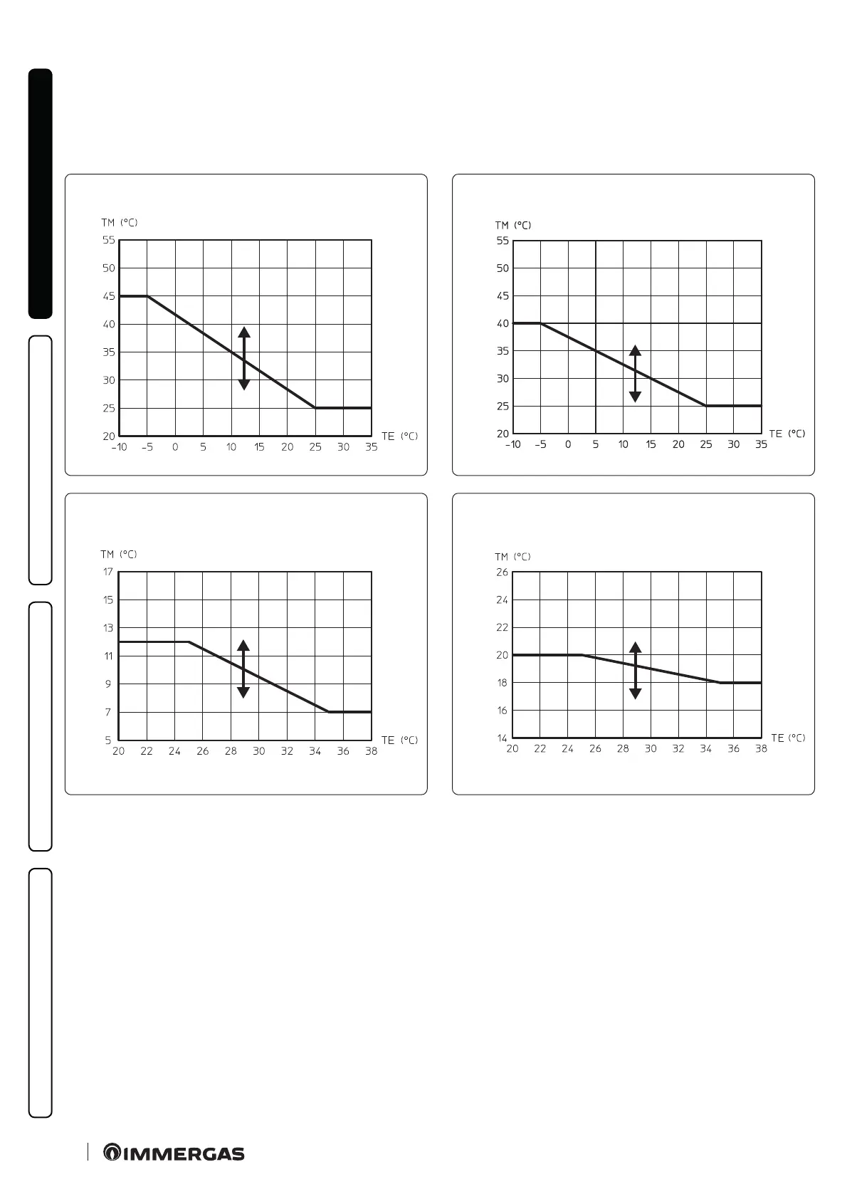
1.17 TEMPERATURE CONTROL SETTING
By setting the parameters in the “Heat regulation” menu, you can
adjust how the system operates.
e curves (Fig. 14, 16, 15, 17, 18, 19) show the default settings in
the various operating modes available both with external probe
and without.
Zone 1 ow temperature in central heating mode
e , w i t h e x t e r n a l p r o b e
R04
R05
R02 R03
U03
14
Zone 1 ow temperature in cooling mode
, with external probe
R13
R12
R11 R10
U05
15
Key (Fig. 14,15,16,17,18,19)
1 - Central Heating Set
2 - Cooling Set
Rxx - “Temperature control” menu parameter
TE - External temperature
TM - Flow temperature
U 01 - Zone 2 ow temperature in "User" menu central heating
mode
U 02 - Zone 2 ow temperature in "User" menu cooling mode
U 03 - Oset value compared to the curve set by the external probe
on central heating zone 1.
U 04 - Oset value compared to the curve set by the external probe
on central heating zone 2.
Zone 2 (3) mixed
ow temperature in central heating mode, with external probe
R08
(R23)
R09
(R24)
R06 (R21) R07 (R22)
(U16)
U04
16
Zone 2 (3) mixed
ow temperature in cooling mode, with external probe
(R28)
R17
R16
(R27)
R15 (R26) R14 (R25)
(U17)
U06
17
U 05 - Oset value compared to the curve set by the external probe
on cooling zone 1
U 06 - Oset value compared to the curve set by the external probe
on cooling zone 2
U 14 - Zone 3 ow temperature in "User" menu central heating
mode
U 15 - Zone 3 ow temperature in "User" menu cooling mode
U 16 - Oset value compared to the curve set by the external probe
on central heating zone 3
U 17 - Oset value compared to the curve set by the external probe
on cooling zone 3
Zx - Heating system zone

 Loading...


