32
INSTALLER
USERMAINTENANCE TECHNICIAN
TECHNICAL DATA
C
33
7
4
6
5
1
2
3
30
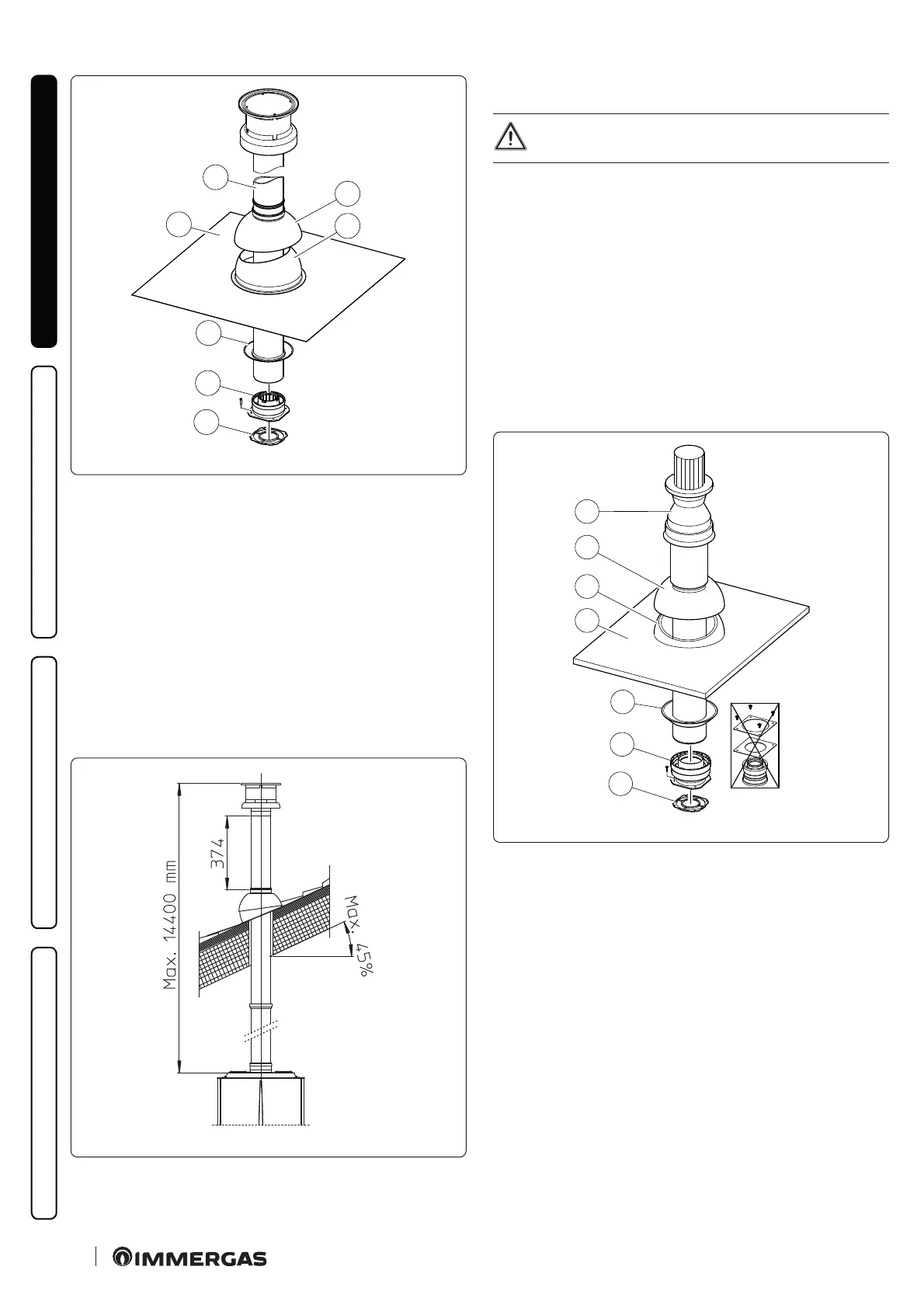
e kit includes (Fig. 30):
No.1 Gasket (1)
No.1 Female concentric ange (2)
No.1 Wall sealing plate (3)
No.1 Aluminium tile (4)
N o .1 I n t a k e / e x h a u s t c o n c e n t r i c p i p e Ø 6 0 /1 0 0 (5)
No.1 Fixed half-shell (6)
No.1 Mobile half-shell (7)
Extensions for Ø 60/100 vertical kit (Fig. 31)
e k i t w i t h t h i s c o n g u r a t i o n c a n b e e x t e n d e d u p t o a m a x . v e r t i -
cal straight length of 14.4 m including the terminal. is congu-
ration corresponds to a resistance factor of 100. In this case specif-
ic extensions must be requested.
C
33
31
Mounting the vertical kit with aluminium tile Ø 80/125
(Fig. 32)
To install the kit Ø 80/125 one must use the anged
adapter kit in order to install the ue system Ø 80/125.
1. Install the concentric ange (2) on the central hole of the in-
door unit, positioning gasket (1) with the circular projections
downwards in contact with the indoor unit ange.
2. Tighten the concentric ange with the screws in the kit.
3. Replace the tiles with the aluminium sheet (4), shaping it to
ensure that rainwater runs o.
4. Position the xed half-shell (5) on the aluminium tile;
5. Insert the intake-exhaust terminal (7);
6. Fit the Ø 80/125 concentric terminal pipe with the male side
(smooth) to the female side of the adapter (1) (with lip seals) up
to the end stop, making sure that the wall sealing plate (3) has
been tted; this will ensure sealing and joining of the elements
making up the kit.
C
33
1
2
3
4
5
6
7
32
e adapter kit includes (Fig. 32):
No.1 Gasket (1)
No.1 Adapter Ø 80/125 (2)
e Kit Ø 80/125 includes (Fig. 32):
No.1 Wall sealing plate (3)
No.1 Aluminium tile (4)
No.1 Fixed half-shell (5)
No.1 Mobile half-shell (6)
No.1 Concentric intake-exhaust terminal Ø 80/125 (7)
e remaining kit components must not be used
 Loading...


