24
INSTALLER
USERMAINTENANCE TECHNICIAN
TECHNICAL DATA
e maximum Resistance Factor allowed corresponds to the re-
sistance encountered with the maximum allowed pipe length for
e a c h t y p e o f Te r m i n a l K i t .
i s i n fo r m at i on a l l ow s c a l c u l at i on s to be ma de to v er i f y t h e p o s-
sibility of setting up various ue congurations.
A
B
20
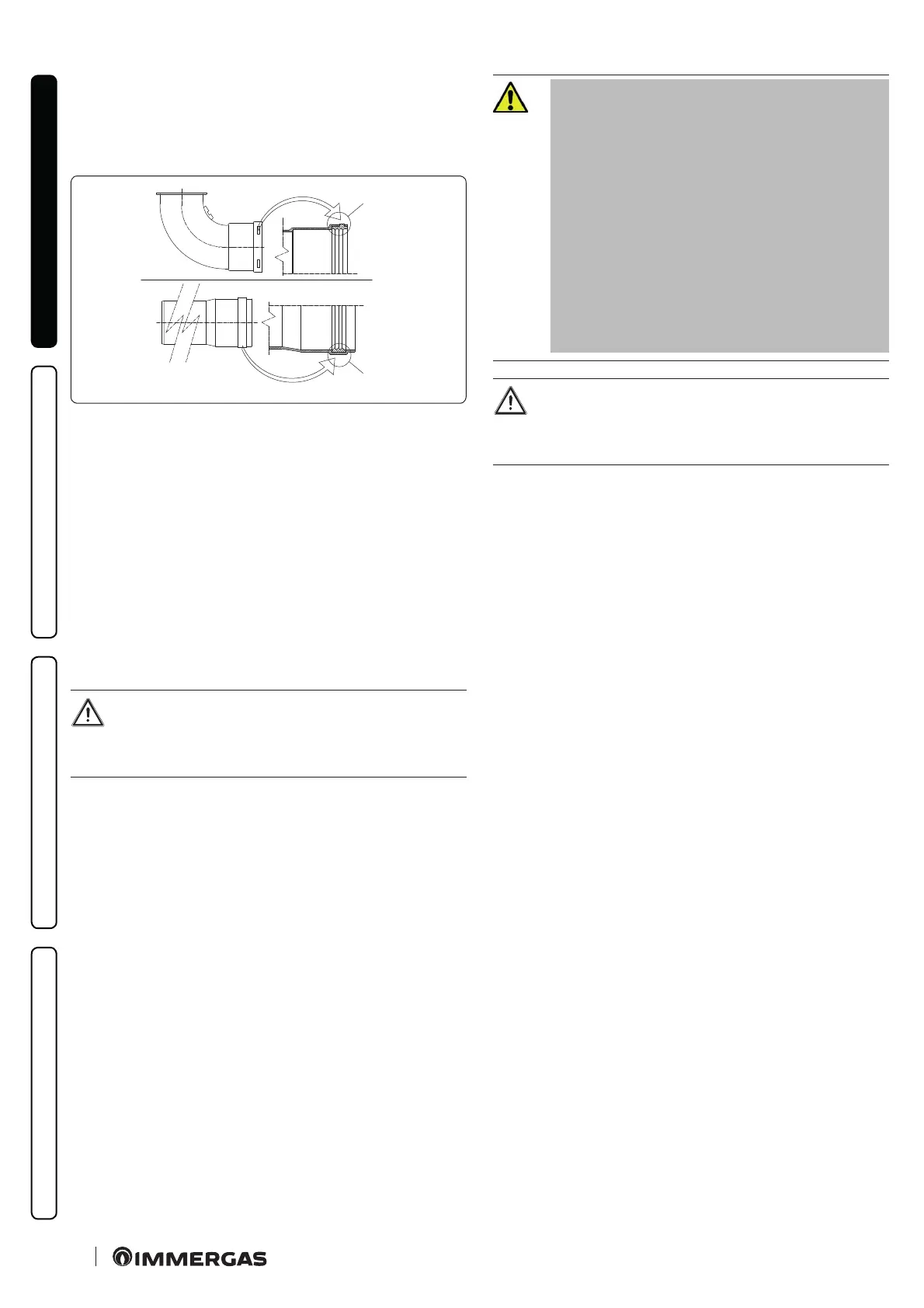
Positioning the gaskets (black) for “green range” ue systems.
Position the gasket correctly (for bends and extensions) (Fig. 20):
- gasket (A) with notches, to use for bends;
- gasket (B) without notches, to use for extensions.
If necessary, to ease the push-tting, spread the elements with
commonly-used talc.
Extension pipes and concentric elbows push-ttings.
To install push-tting extensions with other elements of the ue,
proceed as follows:
- Install the concentric pipe or elbow with the male side (smooth)
on the female side (with lip seal) to the end stop on the previous-
ly installed element in order to ensure sealing eciency of the
coupling.
If the exhaust terminal and/or extension concentric pipe
needs shortening, consider that the internal duct must
always protrude by 5 mm with respect to the external
duct.
For safety purposes, do not obstruct the
indoor unit’s intake/exhaust terminal,
not even temporarily
e various parts of the ue system must
be checked to ensure that they have been
laid in such a way as to prevent the cou-
pled parts from detaching, in particular,
the ue exhaust duct in the Ø80 separa-
tor kit conguration. If the condition de-
scribed above is not adequately guaran-
teed, it will be necessary to use the
appropriate retaining clamp kit.
When installing horizontal pipes, a minimum inclina-
tion of 1.5% towards the indoor unit must be main-
tained, and a section clamp with plug must be installed
every 3 metres.
I n s t a l l a t i o n i n s i d e t h e r e c e s s e d f r a m e
In this mode, install the ue according to your needs using the ap-
propriate pre-sections in the frame to exit from its clearances.

 Loading...


