33
INSTALLER
USERMAINTENANCE TECHNICIAN
TECHNICAL DATA
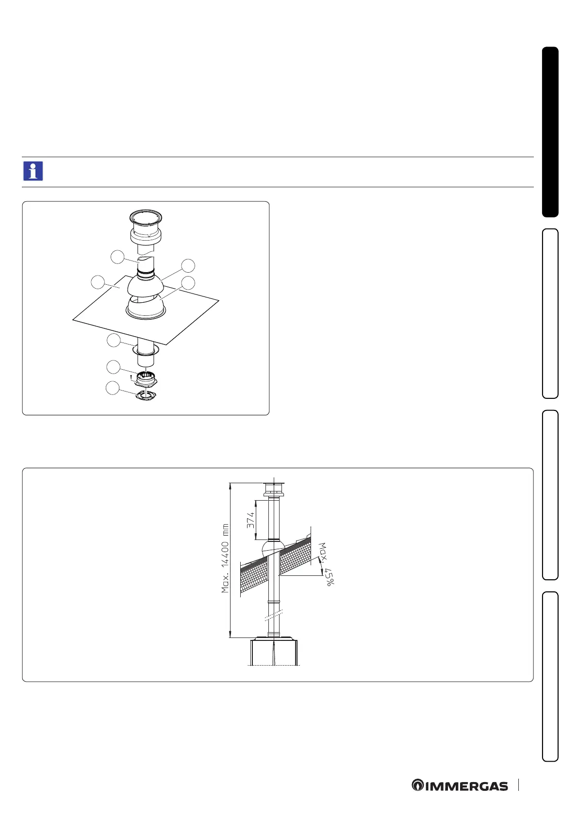
Mounting the vertical kit with aluminium tile Ø 60/100 (Fig. 22)
1. Install the concentric ange (2) on the central hole of the appliance, positioning gasket (1) with the circular projections downwards in
contact with the appliance ange.
2. Tighten the concentric ange with the screws in the kit.
3. Replace the tiles with the aluminium sheet (4), shaping it to ensure that rainwater runs o.
4. Position the xed half-shell (6) on the aluminium tile.
5. Insert the intake-exhaust pipe (5).
6. Fit the Ø 60/100 concentric terminal pipe with the male side (5) (smooth) into the ange (2) up to the end stop, making sure that the
wall sealing plate has been tted (3); this will ensure sealing and joining of the elements making up the kit.
When the appliance is installed in areas where very rigid temperatures can be reached, a special anti-freeze kit is available that
can be installed as an alternative to the standard kit.
C
33
7
4
6
5
1
2
3
22
e kit includes (Fig. 22):
N°1 Ga ske t (1)
N°1 Female concentric ange (2)
N°1 Wall sealing plate (3)
N°1 Aluminium tile (4)
N°1 Concentric intake/exhaust pipe Ø 60/100 (5)
N°1 Fixed half-shell (6)
N°1 Mobile half-shell (7)
Extensions for Ø 60/100 vertical kit (Fig. 23)
e kit with this conguration can be extended up to a max. vertical straight length of 14.4 m including the terminal. is conguration
corresponds to a resistance factor of 100. In this case specic extensions must be requested.
C
33
23