36
INSTALLERUSERMAINTENANCE TECHNICIANTECHNICAL DATA
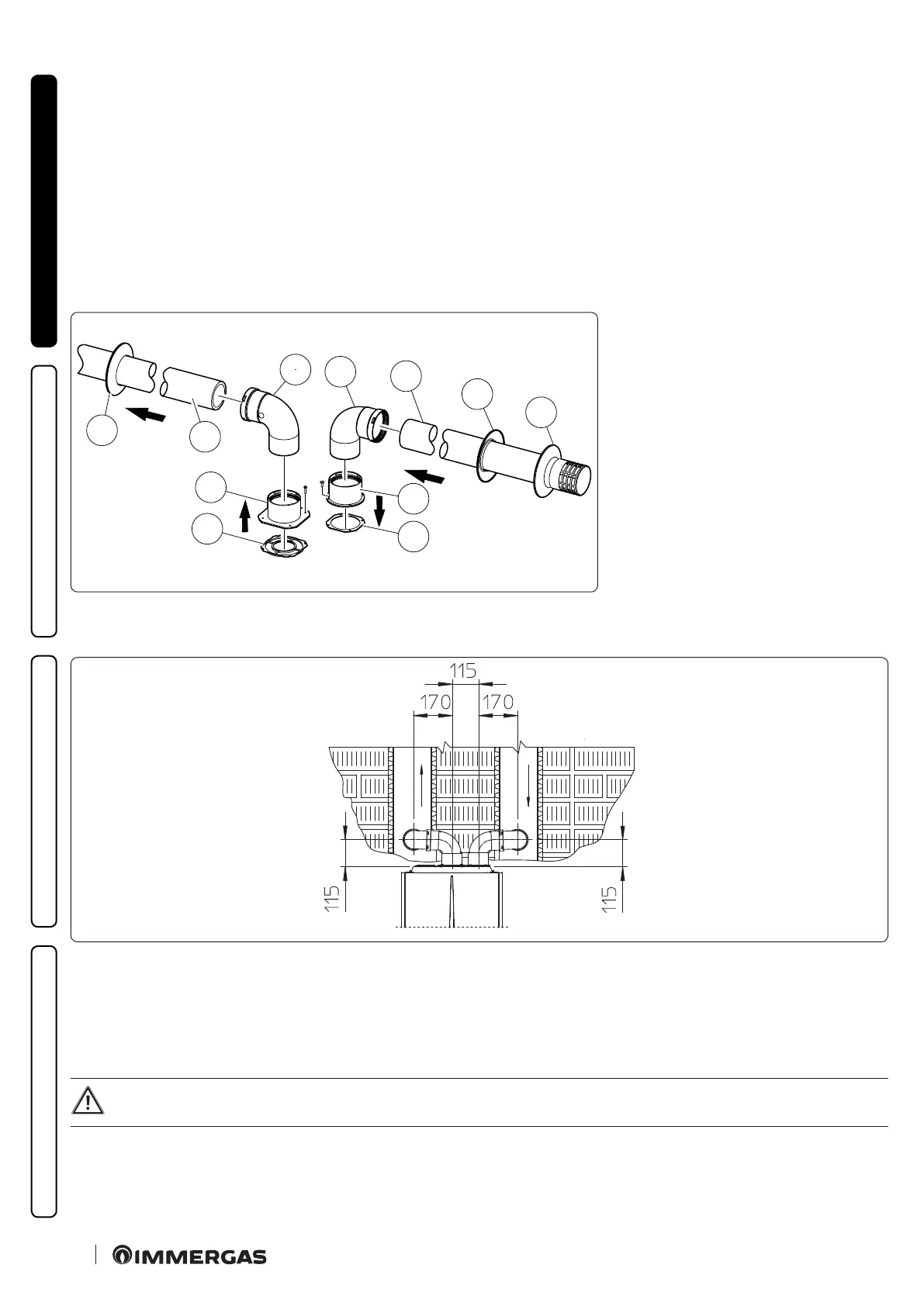
Mounting the separator kit Ø 80/80 (Fig. 26):
1. Install the concentric ange (2) on the central hole of the appliance, positioning gasket (1) with the circular projections downwards in
contact with the appliance ange.
2. Tighten with the hexagonal head and at point screws provided in the kit.
3. Replace the at ange present in the lateral hole with respect to the central one (according to needs) with the ange (3), positioning the
gasket (2) already present in the appliance in between.
4. Tighten with the supplied self-tapping screws with drill bit.
5. Fit the bends with male side (smooth) (5) in the female side of the anges (3 and 4).
6. Fit the intake terminal (6) with the male side (smooth) in the female side of the bend (5) up to the end stop, ensuring that the internal
and external wall sealing plates are tted
7. Fit the exhaust pipe (9) with the male end (smooth) to the female end of the bend (5) up to the end stop; making sure that the internal
wall sealing plate has been tted, this will ensure sealing and joining of the elements making up the kit.
C
53
* - C
83
1
4
7
9
5
5
6
7
8
3
2
S
A
26
e kit includes (Fig. 26):
N°1 Exhaust gasket (1)
N°1 Flange gasket (2)
N°1 Female intake ange (3)
N°1 Female exhaust ange (4)
N°2 Ø 80 90° bend (5)
N°1 Intake terminal Ø 80 (6)
N°2 Internal wall sealing plates (7)
N°1 External wall sealing plate (8)
N°1 Exhaust pipe Ø 80 (9)
* to complete C53 conguration, also pro-
vide for a “green range” roof discharge ter-
minal. e conguration on walls opposite
the building is not allowed.
Installation clearances (Fig. 27)
e minimum installation clearance measurements of the Ø 80/80 separator terminal kit have been stated in some limit conditions.
C
43
27
Extensions for separator kit Ø 80/80
e maximum vertical straight length (without bends) that can be used for Ø 80 intake and exhaust pipes is 41 metres, regardless from
whether they are used for intake or exhaust.
e maximum horizontal straight length (with bend in suction and in exhaust) that can be used for Ø 80 intake and exhaust pipes is 36
metres, regardless from whether they are used for intake or exhaust.
Please note the type of installation C
43
must be done with a natural draught ue.
To aid in the removal of possible condensate forming in the exhaust pipe, tilt the pipes towards the appliance with a minimum
slope of 1.5% (Fig. 28)