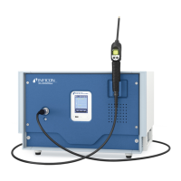
4 | Description INFICON
26 / 108 XL3000flex-Operating-instructions-jina83en1-07-(2105)
Parameter Factory setting
Filter ZERO time 5 s
Filter mode I-Filter
Gas percentage in H
2
(M3, He) 5 % H
2
, 100 % M3, 100% He
Gas ballast Off
I/O module log ASCII
Calibration request On
Calibration factor VAC/SNIF Mx
(for vacuum, sniffing and all masses)
1.0
Cathode selection Auto Cat1
Compatibility mode XL Sniffer Adapter
Config. Analog output 1 Leak rate mantissa
Config. Analog output 2 Leak rate exponent
Config. Analog output scaling 0.5 V / decade
Configuration of digital outputs Pin 1: Trigger 1, inverted
Pin 2: Trigger 2, inverted
Pin 3: Trigger 3, inverted
Pin 4: Trigger 4, inverted
Pin 5: Ready
Pin 6: Error, inverted
Pin 7: CAL request, inverted
Pin 8: Open, inverted
Configuration of digital Inputs Pin 1: Select dyn. / normal CAL
Pin 2: Sniff
Pin 3: Start/Stop, inverted
Pin 4: ZERO
Pin 5: External CAL
Pin 6: Internal CAL
Pin 7: Clear
Pin 8: ZERO update
Pin 9: –
Pin 10: –
Leak rate unit SNIF, (display and interface) mbar l/s
Leak rate unit VAC, (display and interface) mbar l/s
Leak rate upper limit VAC (interface) 1.0 x 10
4
Leak rate lower limit VAC (interface) 1.0 x 10
-12
Leak rate upper limit SNIF (interface) 1.0 x 10
4
Leak rate lower limit SNIF (interface) 1.0 x 10
-8
Fan mode Fan always on
Machine factor in standby Off
 Loading...