Introduction to Digital Power Conversion
XMC4000/1000 Family
Control Loops
Application Guide 79 V1.0, 2015-01
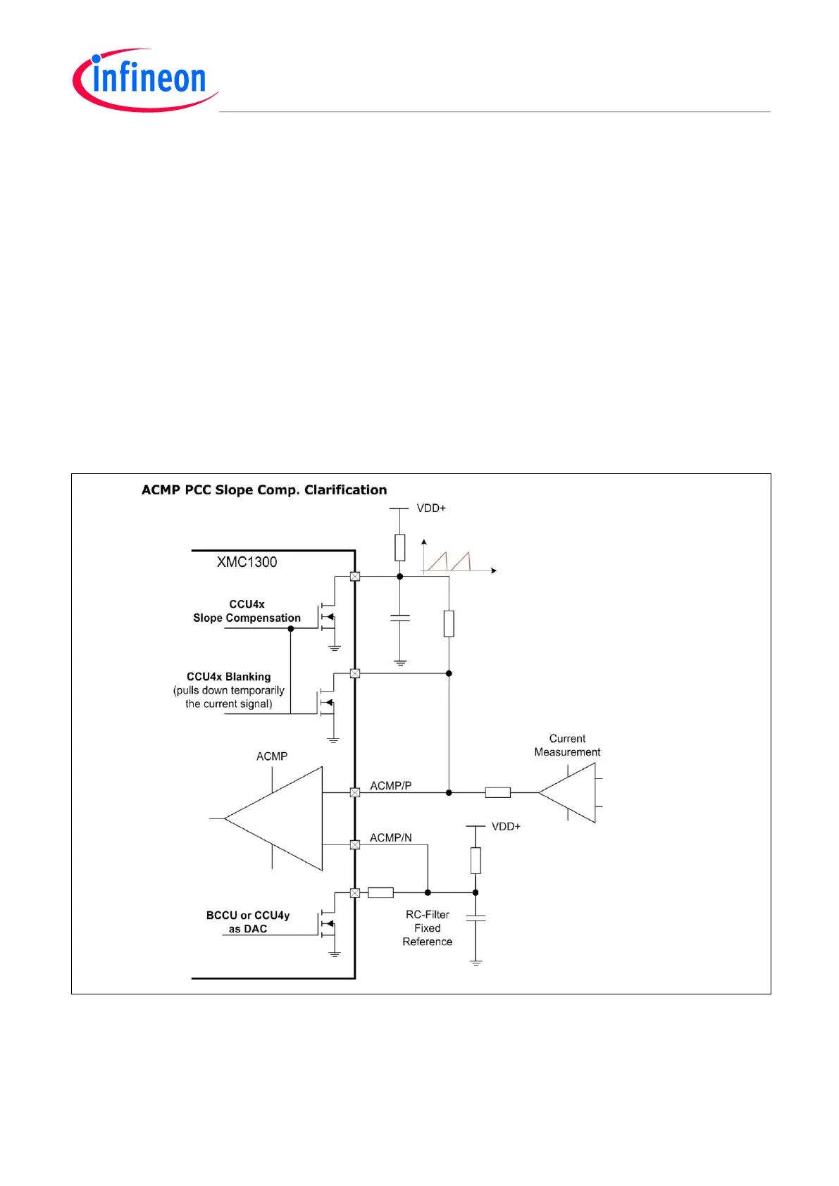
Inductor Current Measurement with Add-On Slope Compensation Ramp (plus Blanking)
A linear ramp (V
SC
) can be created by a capacitor that is charged with a time-constant exceeding the
switch period (T).
The ramp (V
SC
) and the input signal (I
L
*[R
i
]) are added onto the input ACMP/P, for the slope
compensation.
A fixed peak detection reference is applied to ACMP/N from a “CCU 4 as DAC” via RC-filter.
The SC-Ramp is PWM aligned.
Blanking is controlled via ACMP/P.
See Figure 64.
ACMP PCC Slope Compensation Circuit; Clarification Example
By using RC-networks, there is a simple, straight-forward way to accomplish external linear control of
a slope compensation voltage ramp, as well as a fixed reference voltage from a 1-bit DAC using a
low-pass filter. All signals are related to ground – and controlled by CCU outputs in open drain mode.
Figure 64 ACMP PCC Slope Compensation Clarification
Current Measurement Signal
The output voltage of the Current Measurement is assumed to be representing the inductor current.

 Loading...
