Installation and programming manual
Installation instructions 27
6.3 Connecting the Loop
The loop accommodates all the peripheral devices of the fire control system (detectors, callpoints,
modules, etc.), and if necessary, also a Gas Extinguishant Module. For a full description of the devices the
loop accommodates, refer to Appendix A, Appendix B and Appendix C.
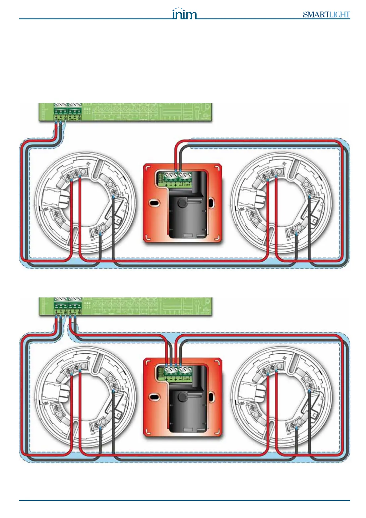
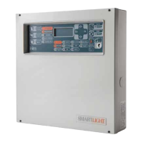
You can use either a 2 or 4 wire connection. To create a 4 wire connection, start on the LOOP-O terminals,
connect all the system devices and re-enter on the LOOP-I terminals. 4 wire connections tolerate one
wiring fault. If loop interruption occurs, the panel will manage the section entering on the LOOP-I terminals
separately, thus splitting the loop in two separate sections.
Figure 11 - 2 wire connection
Figure 12 - 4 wire connection