16 Technical description
Installation and programming manual
Chapter 4
Technical description
4.1 Internal devices
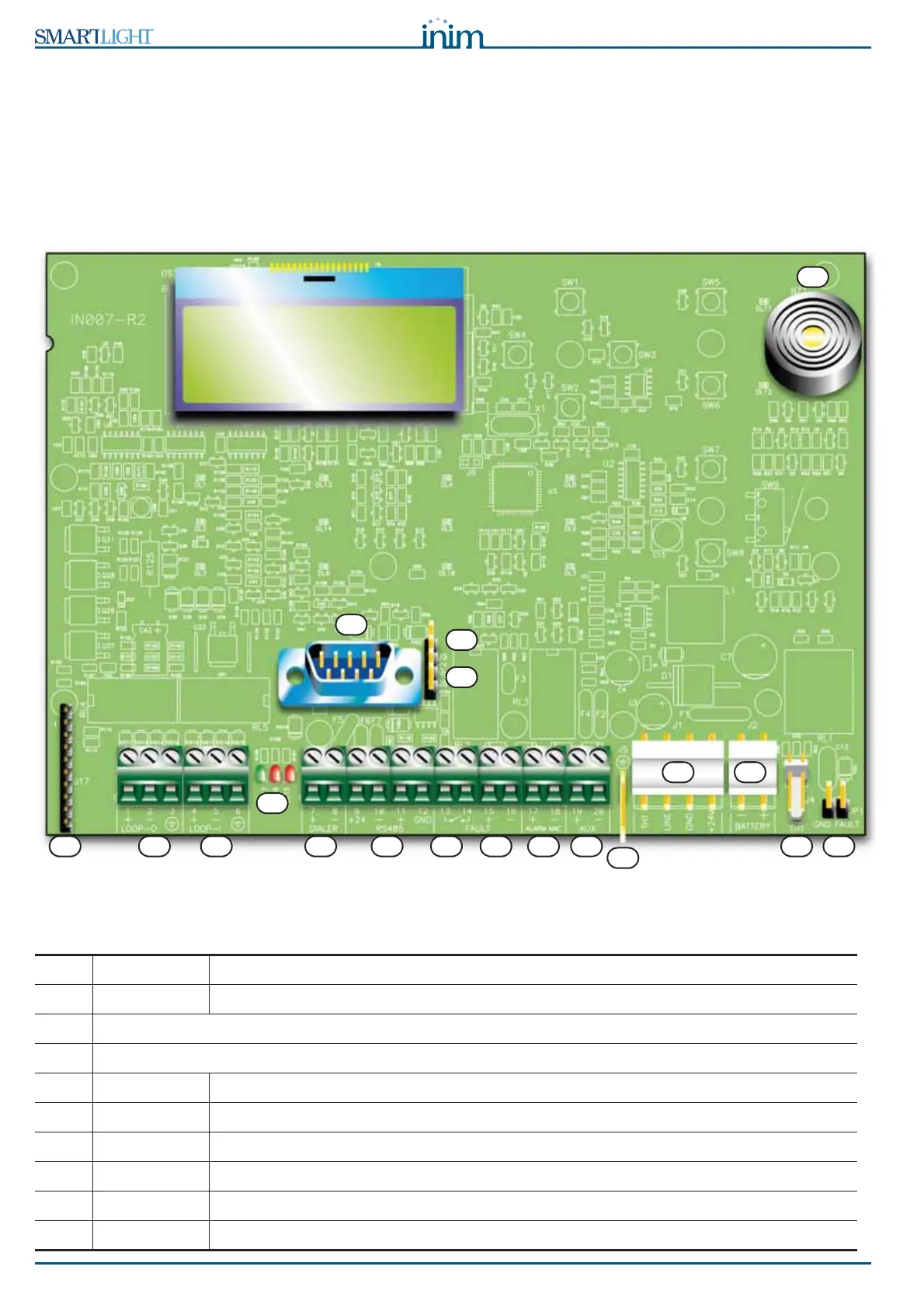
Figure 5 - SmartLight motherboard
Main components
[A] LOOP-O Loop output terminals
[B] LOOP-I Loop input terminals
[C] Loop status LED (refer to Chapter 5 - User Interface)
[D] RS232 serial port for PC connection
[E] DIALER Output terminal for dialer connection, supervised
[F] RS485 RS485 BUS terminals for repeater connections, max. 0.9 A
[G] FAULT Fault output - dry contact
[H] FAULT +/- Fault output - supervised
[I] ALARM NAC Alarm output - supervised
[J] AUX 24 V 0.8A output for external loads
A B
C
D
E F G H I J
K
L M
N O
P
Q
R
S