30 Installation instructions
Installation and programming manual
Attention: All other DIP switch configurations are NOT allowed.
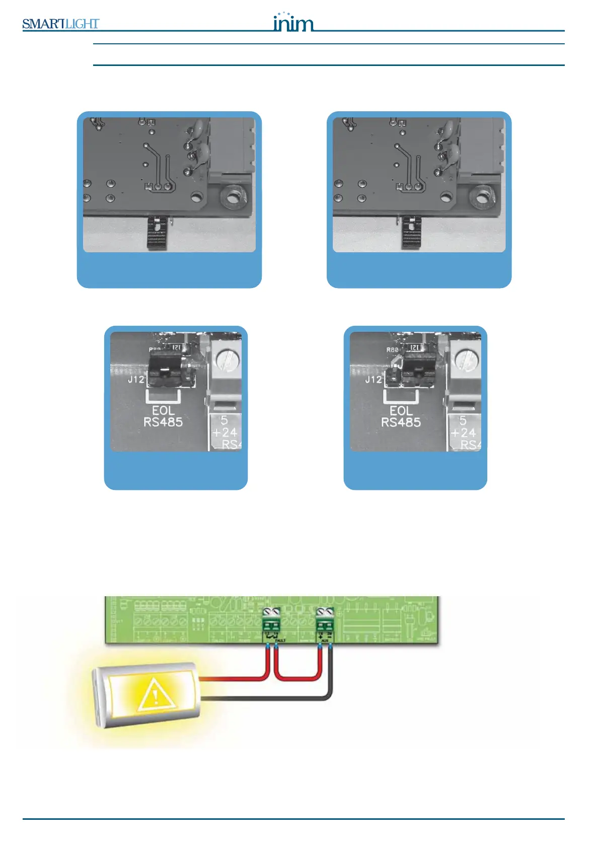
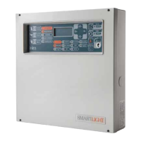
2. Ensure that the EOL jumper (paragraph 5.3.3 - [C]) is set in the EOL position on the last device on the
line ONLY.
Figure 16 - SmartLetUSee/LCD-Lite board - jumper position
Figure 17 - SmartLevel board - jumper position
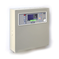
6.6 Connecting the fault signaling outputs
The panel provides 2 fault signaling outputs:
• A normally-open dry contact
• A supervised output protected by a resettable fuse @ 0.3 A
Figure 18 - Normally-open FAULT output connection
EOL jumper position for the
end-of-line repeater
Jumper position for the centrally
positioned repeater
EOL jumper position for the end
power-supply station
Position the jumper in the
central position