32 Installation instructions
Installation and programming manual
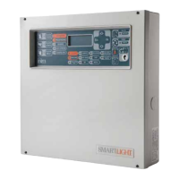
In the event of an alarm, the output will activate and the panel will supply 24 V in accordance with the
polarity indicated on the board.
6.7.1 Wiring
1. Use NON-shielded cable.
The wire section should be compatible with the wire length and load connected to the output.
2. Connect the EOL resistor (47 K:) in parallel to the last device on the line.
3. Connect a 1N4007 diode (or equivalent) in series to each load.
6.8 Connecting the extinguishant module (optional)
Figure 21 - Extinguishant module
A
YELLOW
VIOLET ORANGE
GOLD
BROWN
GREEN ORANGE
GOLD
B
POWER SUPPLY 24V
Gas release
electrovalve
D
YELLOW
VIOLET ORANGE
GOLD
STOP-
EXTINCTION
signalling LED
SmartLight
control panel