Installation and programming manual
Installation instructions 31
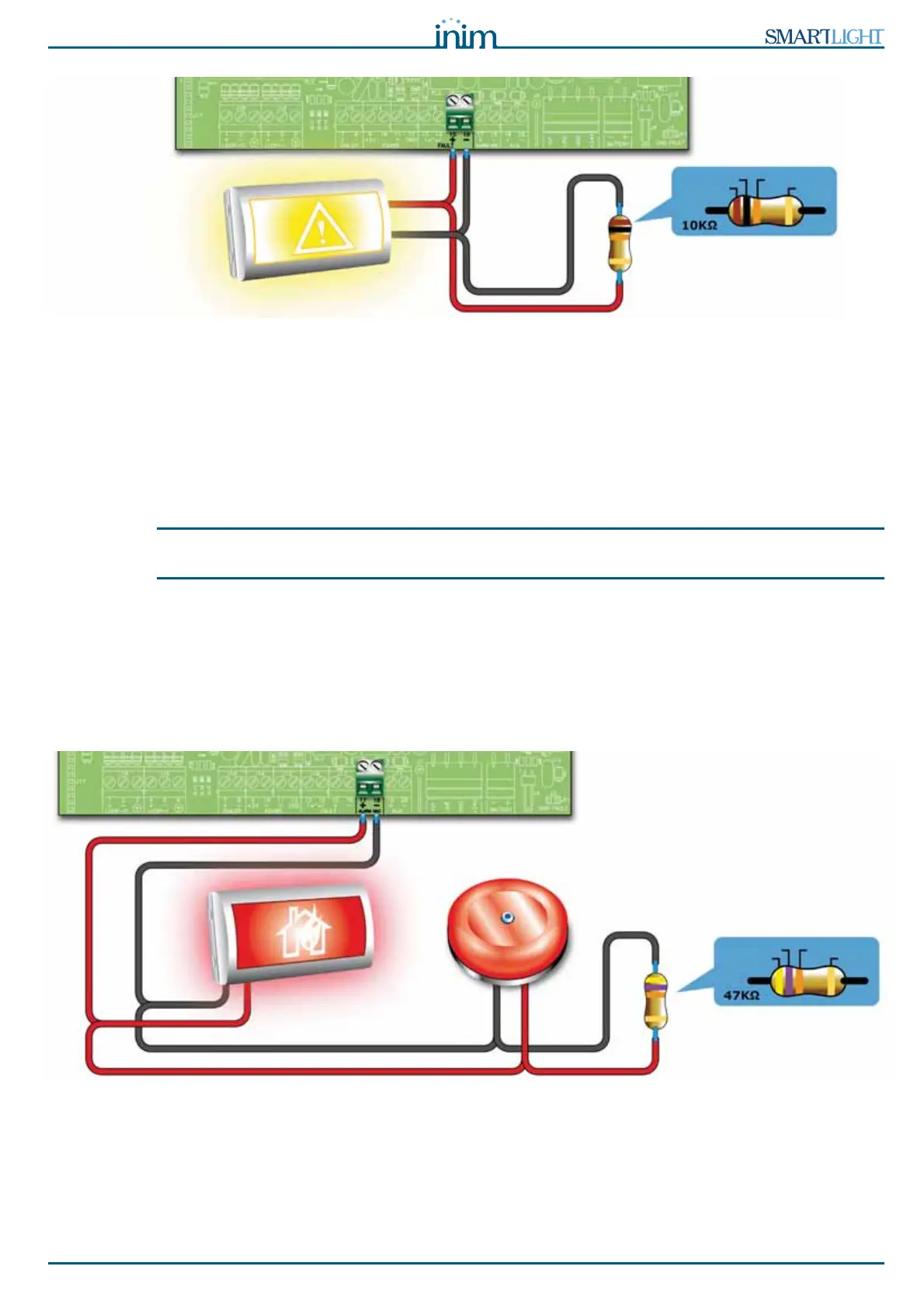
Figure 19 - supervised FAULT output connection
During standby status the voltage applied to the output will be less than 0.5 V, thus not enough to activate
the connected load, but enough to allow the panel to verify the integrity of the connection cable.
Open or shorted conditions on the wires will generate a fault signal: “
Open” or “Shorted Alarm
Output”
.
In the event of a fault, this output will activate, and the panel will supply 24 V in accordance with the
polarity indicated on the board.
Note: In order to validate the IMQ-SECURITY SYSTEMS certification, these outputs must not be used as Type
J outputs (EN 54-1), therefore, they must not be used to command devices that transmit fault signals.
6.6.1 Wiring
1. Use NON-shielded cable.
The wire section should be compatible with the wire length and load connected to the output.
2. Connect the EOL resistor (10 K:) in parallel to the last device on the line.
6.7 Connecting the alarm signaling output
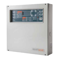
Figure 20 - Connecting the Alarm output
The alarm output is a silenceable supervised output protected by a resettable fuse @ 0.9 A.
During standby status the panel will allow a low supervisory current to circulate on the line with reverse
polarity to that indicated on the board. The diodes connected in series to each load on the line will ensure
that the current closes on the EOL resistor. This current allows the panel to verify cable integrity. Open or
shorted conditions on the wires will generate a fault signal: “
Open” or “Shorted Alarm Output”.
BROWN
BLACK ORANGE
GOLD
FAULT signalling
sign
YELLOW
VIOLET ORANGE
GOLD