Installation and programming manual
Installation instructions 29
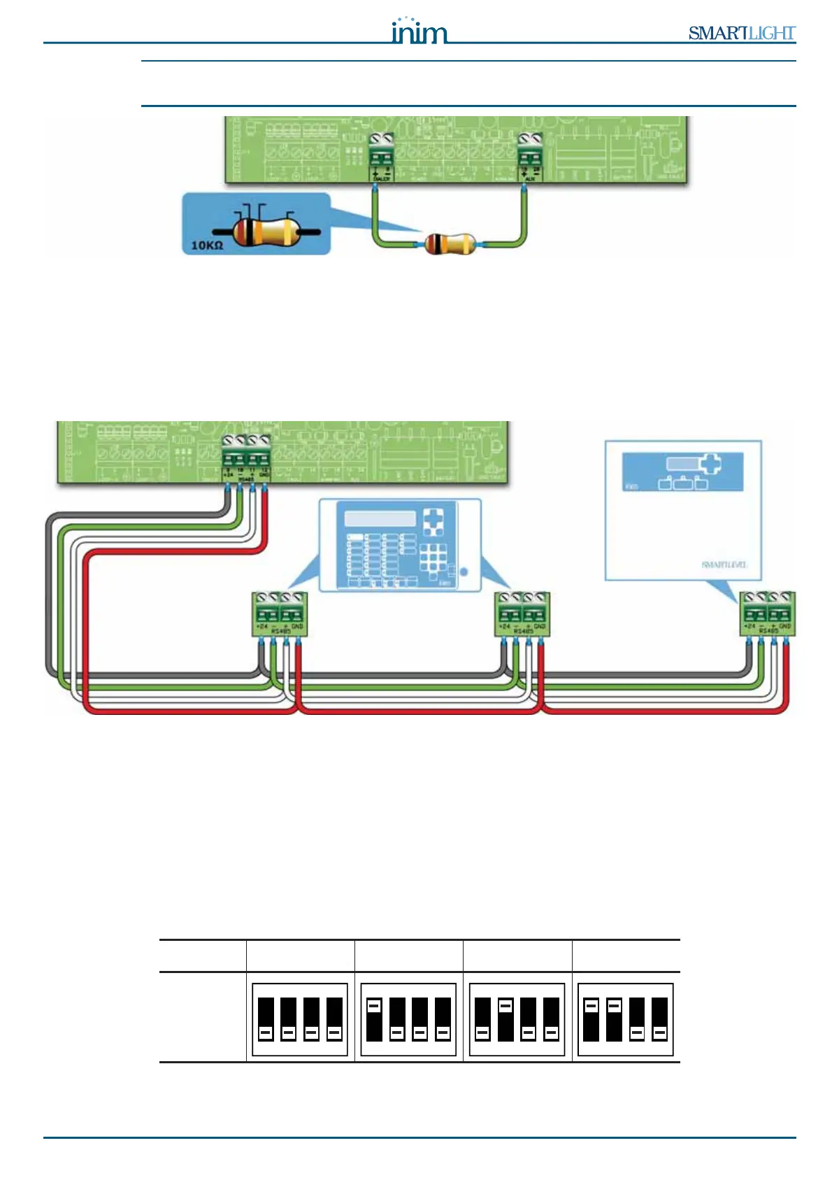
Note: If you do not connect a dialer, the control panel +DIALER output should be connected to the +24V
output by a 10 k
:
resistor.
Figure 14 - +DIALER output connection without dialer
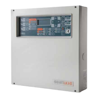
6.5 Connecting the RS485 BUS
The RS485 BUS terminals accept up to 4 SmartLetUSee/LCD-Lite repeaters (remote information points,
generally located in the entrance areas of the protected building) and 2 SmartLevel power stations.
The devices must be connected in parallel. The panel communicates with the repeater panels using a highly
noise-immune digital protocol.
Figure 15 - Connecting the RS485 BUS
6.5.1 Wiring
1. Use a 4 pole STP cable.
2. The cable length between the panel and repeater should not exceed 1000 m.
3. Connect the shield to earth (terminal 6 can be used for this connection).
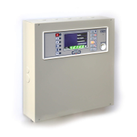
6.5.2 Setting the addresses of devices connected to the RS485 BUS
1. Each of the devices connected to the RS485 BUS must have a distinct address. When setting the
addresses of SmartLevel devices, refer to the Power Station programming manual. When setting the
addresses of repeaters, use the DIP switches (paragraph 5.3.3 - [A]).
Address1234
DIP
Switch
position
BROWN
BLACK ORANGE
GOLD
REPEATERS
SmartLetUSee/LCD-Lite
POWER SUPPLY
STATION
SmartLevel
ON
1 2 3 4