User’s Manual Innomar SES Parametric Sub-bottom Profilers 83
Innomar Technologie GmbH (2020-09) 83
5.5 1-PPS Input
The “1-PPS” pulse is expected at pin 1 of the “Nav IN” connector (serial DB9). On some systems
is an additional dedicated BNC socket for the “1-PPS” pulse.
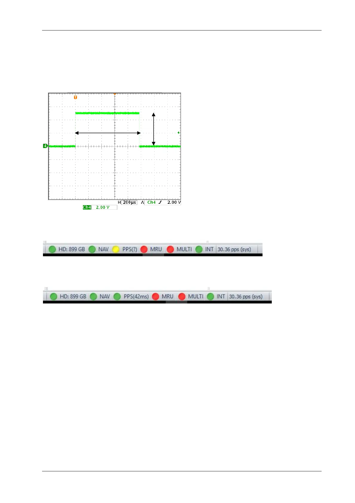
The “1-PPS” pulse needs to be TTL (5V positive) level, pulse width ideally 1ms duration as shown
below.
If such pulse is detected by SESWIN the “PPS” indicator in SESWIN’s status bar turns yellow,
independent on position data available at “Nav IN”.
If a “$xxZDA” message is received within the “NavIn” data, the “PPS” indicator turns green and
the delay between the the “1-PPS” pulse and the next “ZDA” message is shown:
This “1PPS” delay value can be used for quality assurance. Anyhow, there is no correction for
the position data applied based on the “1-PPS” pulse within SESWIN. The delay is not stored
within the INNOMAR SES and RAW data formats, but with the SES3 data format.
!
There is no connection (neither physical nor logical) between the “Sync IN” trigger input
and the “1-PPS” signal.
!
On older systems the “1PPS” was connected to pin 9 of the “Nav IN” socket.
!
The “1PPS” input works only if the position data is fed to the Innomar via the serial RS232
“Nav IN” socket, it is not working if the position data is sent via Ethernet/UDP.
1ms
5V