-12-
2 Product Information
AC800 Series Intelligent Machine Controller Hardware User Guide
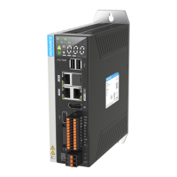
No. Interface Name Description
1 Rear earhook Standard component
2 State indicator For the specic denition of the indicators, see section 2.2.2
3 Display and buttons For specic functions and operations, see section 6
4
Multi-functional expansion
card slot
For CAN/optical ber/RS232/RS485/high-speed I/O
5 Reset Pinhole reset button
6
I/O communication
interface
3 DI/2 DO, RS485/RS232, for details on the pins, see section 5.3.3
7 Power supply terminal 24 V voltage input
8 Fan slot locker Remove this to replace the fan and RTC battery
9 Grounding terminal Controller grounding
10 DVI-D interface Standard DVI-D Display interface
11/12 LAN port 4 LAN ports: 2 for Ethernet and 2 for EtherCAT
13/14 USB Port 2 USB 2.0 ports and 2 USB 3.0 ports
15 Power button Controller startup control
2.2.2 LED State Indicators
The indicators are described as follows:
No. LED Name Function State Denition
1 PWR
Power
indicator
Power status Green
O: abnormal
On: normal
2 RUN
Running
status
indicator
Operational Green
O: user program is not running
Blinking: recognizing device
On: user program is running
3 HDD
Hard drive
indicator
Hard drive state Green
O: no hard drive detected
Blinking: hard drive is working
4 ERR
Error
indicator
Operation error Red
O: normal
Blinking: Low battery
On: 1. overtemperature;
2. user program error;
3. system failure;
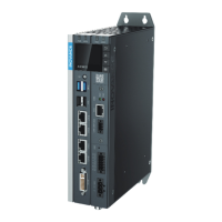
2.2.3 Power Button
The controller power button is located under the front panel of the controller. See the following for the
details:
 Loading...
