-34-
5 Wiring
AC800 Series Intelligent Machine Controller Hardware User Guide
Cable Preparation
$BCMFDPOOFDUPS1$QSPOH
"8($BUFTIJFMEFEUXJTUFEQBJS
$BCMFDPOOFDUPS1$QSPOH
Figure 5 -18 EtherCAT cable preparation
Signal pins
Pin Signal (Ethernet 1000 Mbps) Signal Direction Signal Description
1 TD+ Output Data transmission+
2 TD- Output Data transmission-
3 RD+ Input Data reception+
4 --(DC+*) --(bidirectional) Not used (data C+)
5 --(DC-) --(bidirectional) Not used (data C+)
6 RD- Input Data reception–
7 --(DD+) --(bidirectional) Not used (data D+)
8 --(DD-) --(bidirectional) Not used (data D-)
*Note: The denition of pins 4, 5, 7, and 8 under 1000 Mbps diers from that under 100 Mbps. Pay
attention to the information in parentheses.
■ Length requirements:
When an EtherCAT bus is used, the length of the cable between the devices must not exceed 100 meters.
Exceeding this length will attenuate the signal and aect communication.
■ Technical requirements:
1) 100% continuity test, no short circuit, open circuit, misalignment and poor contact;
2) The cable length is within the allowable tolerance range;
Use a shielded cable as the EtherCAT bus for network data transmission, with the following specications:
Item Specications
Cable type Flexible crossover cable, S-FTP, Cat 5e
Complied standards:
EIA/TIA568A, EN50173, ISO/IEC11801
EIA/TI Abulletin TSB, EIA/TIA SB40-A&TSB36
Conductor cross section AWG26
Conductor type Twisted pair
Pair 4
5.6 Display Interface
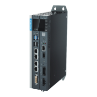
The controller provides a standard DVI-D display interface with the following specications (no cable is
provided):
Item Specications
Signal Type DVI-D (digital signal)
Description 24+1
Number of channels 1
Max. resolution 1920 x 1200 @60Hz
The DVI-D interface is detailed in the following table:
 Loading...
