-14-
2 Product Information
AC800 Series Intelligent Machine Controller Hardware User Guide
(1) system operation
(2) controller status
(3) fault and commissioning
(4) basic controller information: basic hardware information, software version, and IP address
(5) upgrade and download progress
2.2.5 Interfaces
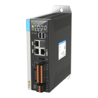
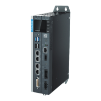
The following table summarizes all the interfaces of the controller:
No. Name Function Description Type
1
Input power
supply
24 VDC (–20% to
+20%)
3-pin pluggable 5.08 Eurostyle terminal, spring crimping,
with xing screws, black
2
I/O
communication
terminal
3DI and 2DO
2 * 6-pin pluggable 3.5 mm Eurostyle terminals, spring
crimping, with xing screws, black
RS485 interface
RS232 interface
3
EtherNET
network port
4 LAN ports: LAN A, LAN B, LAN C and LAN D (top to bottom).
Intel Ethernet controller chip compliant with 802.1Qav, IEEE1588/802.1AS
and 802.3az and Intel® AMT (Intel AMT supports Core i processors with
specic SKU). Four standard RJ-45 Ethernet interfaces. The LED indicators are
described as follows:
Indicator Function Color State Meaning
A:Link/Act Yellow
O:
No connection
Blinking:
Sending and receiving
data
On:
Connected
B:Speed
Green/
orange
O:
1. connection at 10 Mbps
2. no connection
On:
Connection at 100 Mbps
On:
Connection at 1000 Mbps
Description:
Port Function Function
LAN A Ethernet 1
1. System program commissioning
2. User program download and commissioning
3. MODBUS TCP protocol
4.Socket(TCP,UDP)
LAN B Ethernet 2
1. MODBUS TCP protocol
2.Socket(TCP,UDP)
LAN C EtherCAT1
1.EtherCAT protocol
2. auto scan
3. independent axis/IO
LAN D EtherCAT2
1.EtherCAT protocol
2. auto scan
3. independent axis/IO
4
EtherCAT
interface
 Loading...
