-35-
AC800 Series Intelligent Machine Controller Hardware User Guide 5 Wiring
Illustration Pin Signal Pin Signal
1 TMDS data 2- 13 TMDS data 3+
2 TMDS data 2+ 14 +5 V power supply
3 TMDS data 2/4 mask 15 GND (+5 V circuit)
4 TMDS data 4- 16 Hot plug detection
5 TMDS data 4+ 17 TMDS data 0-
6 DDC clock 18 TMDS data 0+
7 DDC data 19 TMDS data 0/5 mask
8
Analog vertical
synchronization
20 TMDS data 5-
9 TMDS data 1- 21 TMDS data 5+
10 TMDS data 1+ 22 TMDS clock mask
11 TMDS data 1/3 mask 23 TMDS clock+
12 TMDS data 3- 24 TMDS clock-
C1
Analog vertical
synchronization
C4
Analog horizontal
synchronization
C2 Analog green C5 AGND (RGB circuit)
C3 Analog blue
It is recommended to use a standard DVI-D cable. If your display does not provide a DVI-D
interface, you can use a DVI to VGA converter.
5.7 USB Port
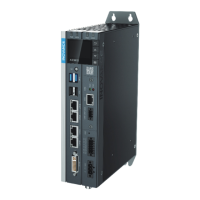
The controller provides 4 USB ports: 2 USB2.0 ports ( ③ and ④ in the gure below), and 2 USB3.0 ports (①
and ② in the gure below).
Figure 5 -19 USB port
The specications of the USB ports are as follows:
Item USB2.0 USB3.0
Max. communication rate 480Mbps 5.0Gbps
Max. output current at 5 V 500mA 900mA
Max. communication
distance
5 m 3 m
Isolated No No
◆ For industrial applications, select industry-level USB devices to ensure reliability.
◆ To prevent interference, avoid long distance connection and run the cable according
to the routing specications.
◆ If interference cannot be removed, install a magnetic ring at both ends of the
communication cable to lter the interference.
 Loading...
