-26-
5 Wiring
AC800 Series Intelligent Machine Controller Hardware User Guide
5.2 Wiring of Power Input Terminal
The power input terminal is a 3-pin screw-xed pluggable terminal with a pitch of 5.08 mm. To facilitate
wiring, replacement and maintenance, use a spring clamp crimping terminal. The following illustration
shows how the power cable connector is inserted into the power input terminal:
Figure 5-5 Wiring of power input terminal
1) Denition of the power terminal
Terminal No. Name Type Function
1 +24 V Input
DC input
positive
2 0 V Input
DC input
negative
3 Grounding Housing PE
2) Specications of input power supply
No. Item Specications
1 Input voltage 24 VDC (–20% to +20%)
2 Input current 3 A
3 Foolproof Yes
4 Short-circuit protection Yes
Note: power input is equipped with a fuse.
3) Power cable preparation
The power input cable uses a pin terminal. For preparation instructions, see section 5.8.
5.3 Wring of I/O Communication Interface
The IO/communication interface is a 12-pin (dual-row) 3.5 mm pitch terminal, which includes UPS
auxiliary signal, RS-232 signal, RS-485 signal, startup signal, PLC program start/stop control signal and
power status signal. Use a screw-xed spring clamp crimping terminal to facilitate wiring, replacement
and maintenance.
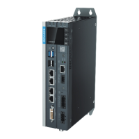
The following illustration shows how the I/O communication cable connector is inserted into the I/O
terminal:
 Loading...
