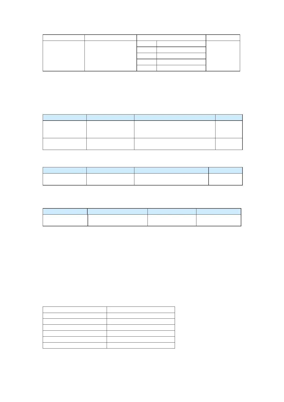
F0-10 Maximum frequency 50.00–150.00 Hz 50.00 Hz
0 Set by F0-12
1 AI1
2 AI2
3 AI3
F0-11
Source of output
frequency upper limit
5 Via communication
0
It is used to define the source of the output frequency upper limit. You can set the output
frequency upper limit in F0-12 or by the AI terminal. If the AI terminal is used, 100% of the
analog input corresponds to F0-12.
For example, to avoid runaway in torque control in winding application, you can set the
output frequency upper limit via analog input. When the AC drive runs to the upper limit, it
will keep running at the output frequency upper limit.
Function Code Name Setting Range Default
F0-12
Output frequency
upper limit
"Lower limit of output frequency"
(F0-14) to "Maximum frequency"
(F0-10)
50.00 Hz
F0-13 Upper limit offset
0.00 Hz to "Maximum frequency"
(F0-10)
0.00 Hz
If the source of the output frequency upper limit is analog setting, the final output
frequency upper limit is obtained by adding the offset in F0-13 to the analog setting.
Function Code Name Setting Range Default
F0-14
Output frequency
lower limit
0.00 Hz to "Output frequency upper
limit" (F0-12)
0.00 Hz
The AC drive starts up from the brake release frequency. If the set frequency is lower than
the lower limit set in F0-14, the AC drive keeps running at the output frequency lower limit
until it stops or the set frequency is higher than the lower limit.
Function Code Name Setting Range Default
F0-15 Carrier frequency 0.5–16.0 kHz Model dependent
It is used to adjust the AC drive’s carrier frequency, aiming to reduce motor noise, avoid
the resonance of the mechanical system, and reduce the leakage current to the earth and
the interference generated by the AC drive.
z When the carrier frequency is low, the current high harmonic output, power loss of the
motor, and motor temperature rise increase.
z When the carrier frequency is high, the power loss of the motor declines and motor
temperature rise decline. However, the AC drive has an increase in power loss,
temperature rise and interference.
Adjusting the carrier frequency will exert influences on the aspects listed in the following
table.
Table 6-1 Influences of carrier frequency adjustment
Carrier frequency Low………………………..High
Motor noise Large……………………..Small
Output current waveform Bad………………………..Good
Motor temperature rise High……………………..…Low
AC drive temperature rise Low…………………………High
Leakage current Small………………………Large
External radiation interference Small………………………Large
efesotomas
on.com

 Loading...


