outputs the brake release command after the delay set in FA-29.
When the system slows down and applies the brake but the brake output conditions are
not satisfied, the AC drive outputs the brake apply command first. After the delay set in
FA-30, the AC drive outputs the low-speed shaft brake apply command.
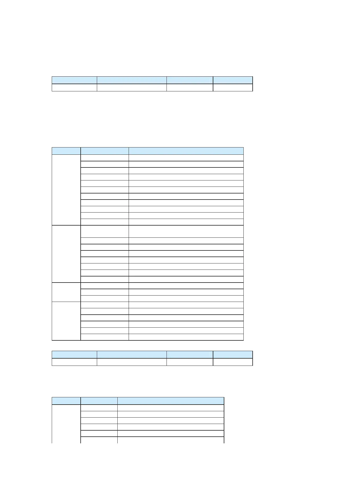
Function Code Parameter Name Setting Range Default
FA-34
Terminal status indication / /
FA-34 indicates the I/O terminal status. The 7-segment LEDs on the operation panel from
left to right are 5, 4, 3, 2 and 1. LED2, LED3 and LED4 indicate the status of I/O terminals
of the CS500, expressed by the segment. LED1 indicates the program running step status,
expressed by the number. LED5 is reserved.
The segments of each LED are explained in the following table.
Table 6-5 Meaning of segments of each LED for I/O terminals
Function Code Parameter Name Setting Range Default
FA-35
Internal variable status / /
The LEDs have the same definition as FA-34. The segments of each LED are explained in
the following table.
Table 6-6 Meaning of segments of each LED for internal variables
LED Segment Meaning of ON
A Current FWD active
B Current REV active
C Multi-speed 1 active
D Multi-speed 2 active
E Multi-speed 3 active
F RUN enabled signal active
LED Display/Segment Meaning of ON
0 Standby status
1 Running status data collection
2 Reserved
3 Reserved
4 Acceleration running handling
5 Jog
6 Reserved
7 Reserved
8 Fault remedy
9 Deceleration running handling
LED1
A to C Reserved
A
DI1 input active (the NO terminal becomes
closed, and the NC terminal becomes open.)
B DI2 input active
C DI3 input active
D DI4 input active
E DI5 input active
F DI6 input active
G DI7 input active
LED2
DP DI8 input active
A DI9 input active
B DI10 input active
LED3
C to DP Reserved
A FMR output active
B Relay1 output active
C Relay2 output active
D DO1 output active
E DO2 output active
LED4
C to DP Reserved
efesotomas
on.com

 Loading...


