Quad-Core Intel® Xeon® Processor 5300 Series Datasheet 31
Electrical Specifications
Notes:
1. Unless otherwise noted, all specifications in this table are based on final silicon characterization data.
2. These voltages are targets only. A variable voltage source should exist on systems in the event that a
different voltage is required. See Section 2.5 for more information.
3. The voltage specification requirements are measured across the VCC_DIE_SENSE and VSS_DIE_SENSE
lands and across the VCC_DIE_SENSE2 and VSS_DIE_SENSE2 lands with an oscilloscope set to 100 MHz
bandwidth, 1.5 pF maximum probe capacitance, and 1 MΩ minimum impedance. The maximum length of
ground wire on the probe should be less than 5 mm. Ensure external noise from the system is not coupled
in the scope probe.
4. The processor must not be subjected to any static V
CC
level that exceeds the V
CC_MAX
associated with any
particular current. Failure to adhere to this specification can shorten processor lifetime.
5. I
CC_MAX
specification is based on maximum V
CC
loadline Refer to Figure 2-12 for details. The processor is
capable of drawing I
CC_MAX
for up to 10 ms. Refer to Figure 2-5, Figure 2-2, and Figure 2-3 for further
details on the average processor current draw over various time durations.
6. FMB is the flexible motherboard guideline. These guidelines are for estimation purposes only. See
Section 2.13.1 for further details on FMB guidelines.
7. This specification represents the total current for GTLREF_DATA_MID, GTLREF_DATA_END,
GTLREF_ADD_MID, and GTLREF_ADD_END.
8. V
TT
must be provided via a separate voltage source and must not be connected to V
CC
. This specification is
measured at the land.
9. Minimum V
CC
and maximum I
CC
are specified at the maximum processor case temperature (T
CASE
) shown
in Figure 6-1.
10. This specification refers to the total reduction of the load line due to VID transitions below the specified
VID.
11. Individual processor VID values may be calibrated during manufacturing such that two devices at the same
frequency may have different VID settings.
12. This specification applies to the VCCPLL land.
13. Baseboard bandwidth is limited to 20 MHz.
14. I
CC_TDC
is the sustained (DC equivalent) current that the processor is capable of drawing indefinitely and
should be used for the voltage regulator temperature assessment. The voltage regulator is responsible for
monitoring its temperature and asserting the necessary signal to inform the processor of a thermal
excursion. Please see the applicable design guidelines for further details. The processor is capable of
drawing I
CC_TDC
indefinitely. Refer to Figure 2-2, Figure 2-3, and Figure 2-5,for further details on the
average processor current draw over various time durations. This parameter is based on design
characterization and is not tested.
15. This is the maximum total current drawn from the V
TT
plane by only one processor with R
TT
enabled. This
specification does not include the current coming from on-board termination (R
TT
), through the signal line.
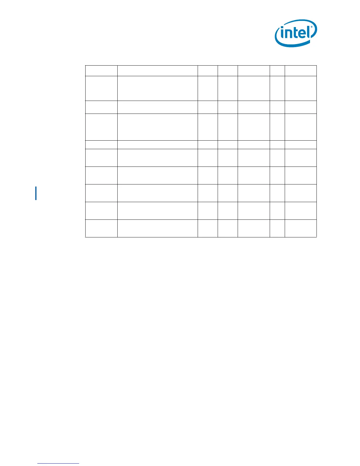
I
CC_TDC
Thermal Design Current (TDC)
Quad-Core Intel® Xeon® Processor
L5318
Launch - FMB
45
A6,14
I
CC_VTT_OUT
DC current that may be drawn from
V
TT_OUT
per land 580 mA 16
I
CC_GTLREF
I
CC
for
GTLREF_DATA_MID,
GTLREF_DATA_END,
GTLREF_ADD_MID,
GTLREF_ADD_END
200 µA 7
I
CC_VCCPLL
I
CC
for PLL supply 260 mA 12
I
TCC
ICC for Quad-Core Intel® Xeon®
Processor E5300 during active
thermal control circuit (TCC)
90 A
I
TCC
I
CC
for Quad-Core Intel® Xeon®
Processor X5300 Series during
active thermal control circuit (TCC)
125 A
I
TCC
I
CC
for Quad-Core Intel® Xeon®
Processor X5365 Series during
active thermal control circuit (TCC)
150 A
I
TCC
I
CC
for Quad-Core Intel® Xeon®
Processor L5300 Series during
active thermal control circuit (TCC)
60 A
I
TCC
I
CC
for Quad-Core Intel® Xeon®
Processor L5318 during active
thermal control circuit (TCC)
50 A
Table 2-12. Voltage and Current Specifications (Sheet 3 of 3)
Symbol Parameter Min Typ Max Unit Notes
1,11