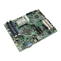
Appendix B: Integrated BMC Sensor Tables Intel® Server Board S2400SC TPS
Intel order number G36516-002 Revision 2.0
Full Sensor Name
(Sensor name in SDR)
Contrib. To
System Status
Voltage Memory AB VDDQ
(BB +1.35 P1LV AB)
E4h All
Voltage
02h
Threshold
01h
[u,l] [c,nc]
Degraded
c = Non-fatal
As and
De
Analog R, T A –
Voltage Memory CD VDDQ
(BB +1.35 P1LV CD)
E5h All
Voltage
02h
Threshold
01h
[u,l] [c,nc]
Degraded
c = Non-fatal
As and
De
Analog R, T A –
Voltage Memory AB VDDQ
(BB +1.35 P2LV AB)
E6h All
Voltage
02h
Threshold
01h
[u,l] [c,nc]
Degraded
c = Non-fatal
As and
De
Analog R, T A –
Voltage Memory CD VDDQ
(BB +1.35 P2LV CD)
E7h All
Voltage
02h
Threshold
01h
[u,l] [c,nc]
Degraded
c = Non-fatal
As and
De
Analog R, T A –
Power Good
(BB +3.3 RSR1 PGD)
EAh
Platform
Specific
Voltage
02h
Threshold
01h
[u,l] [c,nc]
Degraded
c = Non-fatal
As and
De
Analog R, T A –
Power Good
(BB +3.3 RSR2 PGD)
EBh
Platform
Specific
Voltage
02h
Threshold
01h
[u,l] [c,nc]
Degraded
c = Non-fatal
As and
De
Analog R, T A –
Hard Disk Drive 1 -15 Status
(HDD 1 - 15 Status)
F0h
-
FEh
Chassis-
specific
Drive Slot
0Dh
Sensor
Specific
6Fh
As and
De
–
Trig
Offset
A X
progress
Degraded
Notes:
1. Redundancy sensors will be only present on systems with appropriate hardware to support redundancy (for instance, fan or power supply).
2. 2: This is only applicable when the system doesn't support redundant fans. When fan redundancy is supported, then the contribution to system state
is driven by the fan redundancy sensor.
 Loading...


