48
Operating Install Wizard
ü
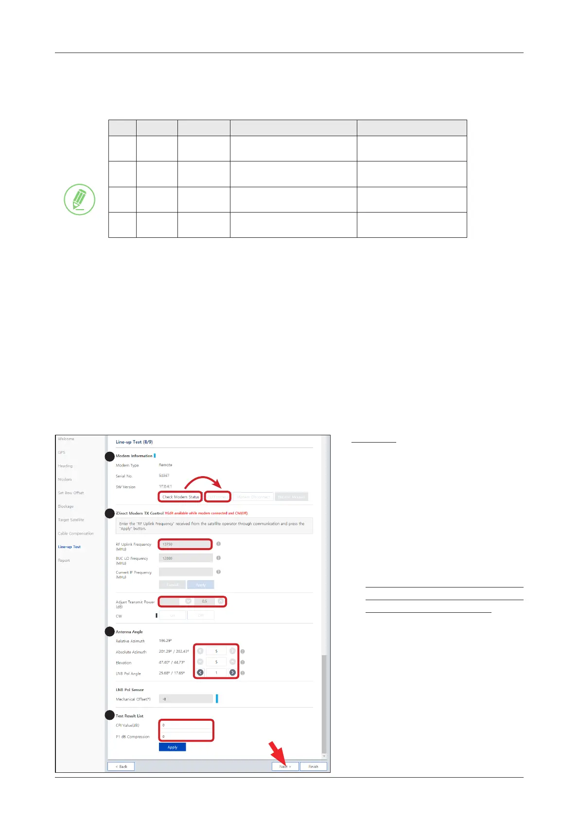
Step 8: Line-up Test
Perform a line-up test by the satellite operator to conrm antenna performance and operation status.
(Option 1: Using iDirect Open AMIP Modem)
Description
1. Check modem status for connection
readiness by clicking the "Check
Modem Status" button. Then
connect to iDirect Open AMIP
modem by clicking the "CLI
Connect" button.
2. Enter the "RF Uplink Frequency"
received from the satellite
operator through communication
and click the "Apply" button.
This menu can be edited when the
antenna is connected to iDirect Open
AMIP modem and the CW is off.
3. Adjust the "Transmit Power" of
the frequency using the arrow keys
which increases or decreases by
0.5dBm.
4. Adjust the "Antenna Angle".
5. Enter the "Test Result" value
received from the satellite operator
and click the "Apply" button.
If you have no problems, click the
"Next" button.
1
2
3
5
NOTE
NOTE. A
The "Cable Compensation Range" is determined by the condition of installation (Modem, BUC). There
exist four cases of cable compensation as follows.
Case Modem* BUC M&C** Compensation Method Compensation path
1 iDirect O
IF signal Source: iDirect
Output Power monitor: BUC M&C
Full path Calibration
2 iDirect X
IF signal Source: iDirect
Output Power monitor: Stacker
Exclude calibration:
BUC
3 iDirect O
IF signal Source: De-stacker
Output Power monitor: BUC M&C
Exclude calibration:
Modem to ACU Cable
4
Not use
iDirect
X
IF signal Source: De-stacker
Output Power monitor: Stacker
Exclude calibration:
Modem to ACU Cable, BUC
*Modem: iDirect X5, X7 Series which are able to access Telnet and support CLI.
**BUC: NJRC, Terrasat products which have M&C function.
NOTE. B
The "Attenuator Graph" displays attenuator values corresponding to the frequency.
• Frequency Range: 950 ~ 1700 MHz(@ 50 MHz step)
• Attenuator Range: 0 ~ 31.5 dB
 Loading...