Working with ENG: EO425 Page 29
ENG/DLB Instruction for Use - English
Date: 2011-09-27 Page 29
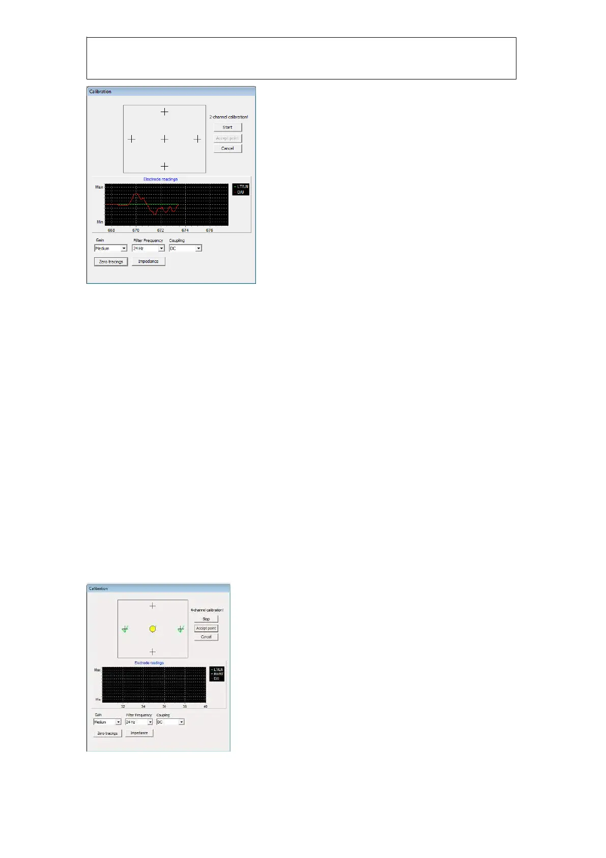
Figure 1.17 Electrode gain readings
The “Electrode readings” graph shows the raw readings from the electrodes. Tracings are in green,
white and red as indicated on the electrode connector. When running in 2-channel mode you will
only see LT/LN and D/U. If you see a lot of noise in the readings you need to check to electrodes
again.
Before starting a calibration you can adjust the gain if the responses from the electrodes are too
low or too high. Ask the patient to look left/right up/down to adjust the gain correctly. The tracings
must not “hit” the max or min markings on the graph. If they do, you need to select a lower gain.
Typically you select the medium gain setting. Filter frequency is default to 24Hz and coupling is set
to DC. You do not need to change these values. Once the gain has been set you click “Start” to
perform a calibration. The calibration procedure requires a minimum of 1 unit on the graph
(horizontal lines) between two calibration points. So if you are having trouble to get the calibration
to accept a point either your gain is too low or you have too much signal noise. You can manually
click “Accept point” if the calibration cannot accept the point automatically.
It is important that you connect the electrodes correctly, do not reverse LT/LN, RN/RT, or D/U. The
calibration will not work if you do so.
Calibration
After the impedance test is complete you need to calibrate. The procedure is the similar to the VNG
calibration, and the patient is instructed to look at each of the 5 dots. A green check mark will
appear when the calibration angle is verified.
Figure 1.18 calibration interface