19
6.1.2 Thermostatic radiator valves
6.1.1 Expansion vessel
► Flush the central heating system thoroughly.
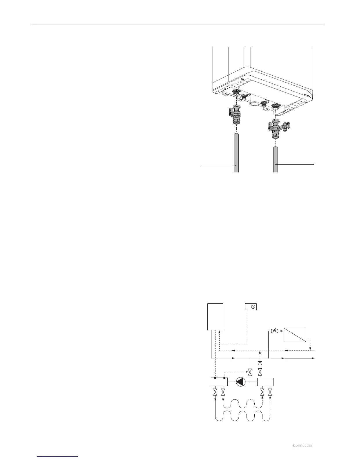
► Fit the flow and return pipes to the isolation valves.
► All pipes must be fitted unstressed in order to prevent pipes
from ticking.
► Existing connections must not be twisted, in order to avoid
leakages.
The CH system should be equipped with:
► A drain tap in the return pipe immediately below the
appliance.
► A drain tap at the lowest point(s) of the installation.
► A non return valve, if pipes run upwards at a short
distance from the appliance. This avoids the occurrence of
thermosyphon eect during DHW operation mode.
If all radiators have thermostatic radiator valves or valves that
can be closed to separate the flow completely from the return,
a minimum amount of water circulation must be ensured by
the installation of bypass piping, for example (also see §8.5).
The appliance is fitted with a expansion vessel adequate for a
system with a water volume not exceeding 100 litres, typically 8
radiators. For larger volume systems, an additional expansion
vessel must be fitted. Contact Intergas for advice in these cases.
6 CONNECTION
6.1.3 Floor heating
Floor heating with pump
For eective operation of the DHW supply any undesired
circulation through the appliance as a result of a second pump
in the CH circuit must be avoided.
Connect the floor heating system in a hydraulically neutral
manner to the appliance, or equip the CH circuit with an
electric shut-o valve or check valve to prevent flow
through the appliance when there is no CH request for heat.
Make sure there is a minimum of water circulation; see §8.5.
Underfloor heating connection diagram
A. Boiler
B. Central heating pump
C. Thermostatic control valve
D. Spring-operated non-return valve
E. Electric shut-o valve 230V~
F. Radiators
G. Room/clock thermostat
H. Maximum thermostat
A
G
H
F
C
B
C
E
D
6.1 Connecting the central heating system
Return pipe
Flow piping