57
A. Switch o the boiler.
A line
– will appear on the right display and the central heating
pressure will be visible on the le display.
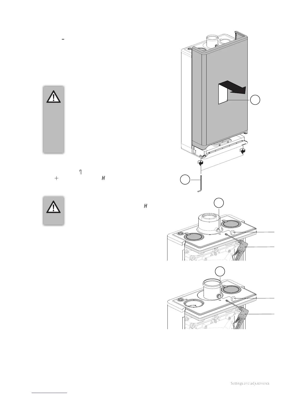
B. Remove the front panel of the boiler by unscrewing the 2
attachment screws (1) and then removing the panel forward (2).
C. Remove the cap of the flue gas measurement point (3) on the
flue adapter above the boiler.
D. Place the analyser probe of the flue gas analyser in the flue gas
measurement point.
IMPORTANT
► Make sure that the flue gas analyser is
calibrated. The start-up procedure of
the flue gas analyser must be completed
before the analyser probe is placed in the
flue gas measurement point.
► The analyser probe must completely seal
o the flue gas measurement point to
provide a reliable measurement.
► The end of the analyser probe must be
located entirely in the flue gases (middle
of the flue gas pipe).
IMPORTANT
► Make sure that the capital letter H
appears on the right display. This
provides assurance that the boiler is
operating as maximum load.
E. Switch on the boiler.
F. Switch on the boiler to maximum output. To do this, hold the
Service button and at the same time tap the Plus button
2x until the capital letter H appears on the right display.
G. Wait until the readout of the flue gas analyser is stable (at
least 3 minutes).
H. Note the measured O
2
(H) or CO
2
(H) value.
O
2
(H) ... = measured maximum output O
2
value
CO
2
(H) ... = measured maximum output CO
2
value
I. Check according to Table 2a or Table 2b whether the
measured maximum output O
2
(H) or CO
2
(H) value is
between the indicated upper and lower limits.
8.10 Inspection of gas air control
8.10.1 Measuring flue gas at maximum output
1
2
Cap
Flue gas
analyser
Flue gas
analyser
Cap
3
3