31
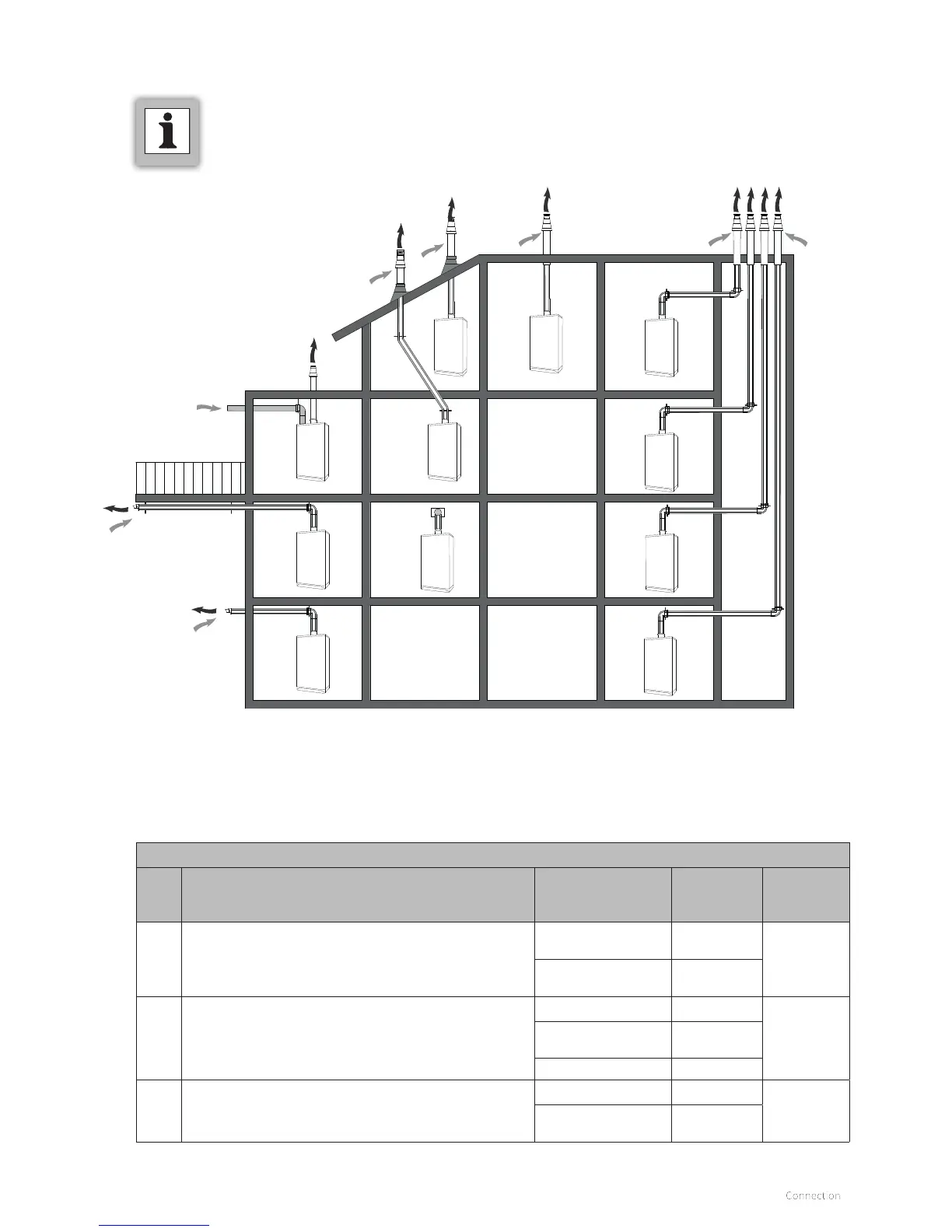
6.8 General layout of the flue
C33
C53
C13
C13
C33
C33
C13
C33
C33
C33
C33
The following drawing shows all possible situations schematically.
COMMENT
► The following schematic drawings serve
as examples and the details may dier
from the actual situation.
Note for flue systems
Cat. Note according to CE Materials
Supplier/
Inspection
requirement
Applicable
to Xtreme
C13 The terminal is located in the façade; the inlet for the air
supply duct is located in the same pressure area as the
terminal. Example: combined façade terminal
Terminal Intergas
Yes
Other components Gastec QA or
Intergas
C33 The terminal is located above the roof; the inlet for the air
supply duct is located in the same pressure area as the
terminal of the flue piping.
Terminal Intergas
Yes
Terminal at the
prefab chimney
Gastec QA or
Intergas
Other components
C53 Closed unit, connected to separate air supply duct and
flue channels, terminated in various pressure zones. See
the installation manual for the possibilities.
Intake grille Intergas
Yes
Other components
and exhaust cap
Gastec QA or
Intergas