25
6.3 Electrical connection
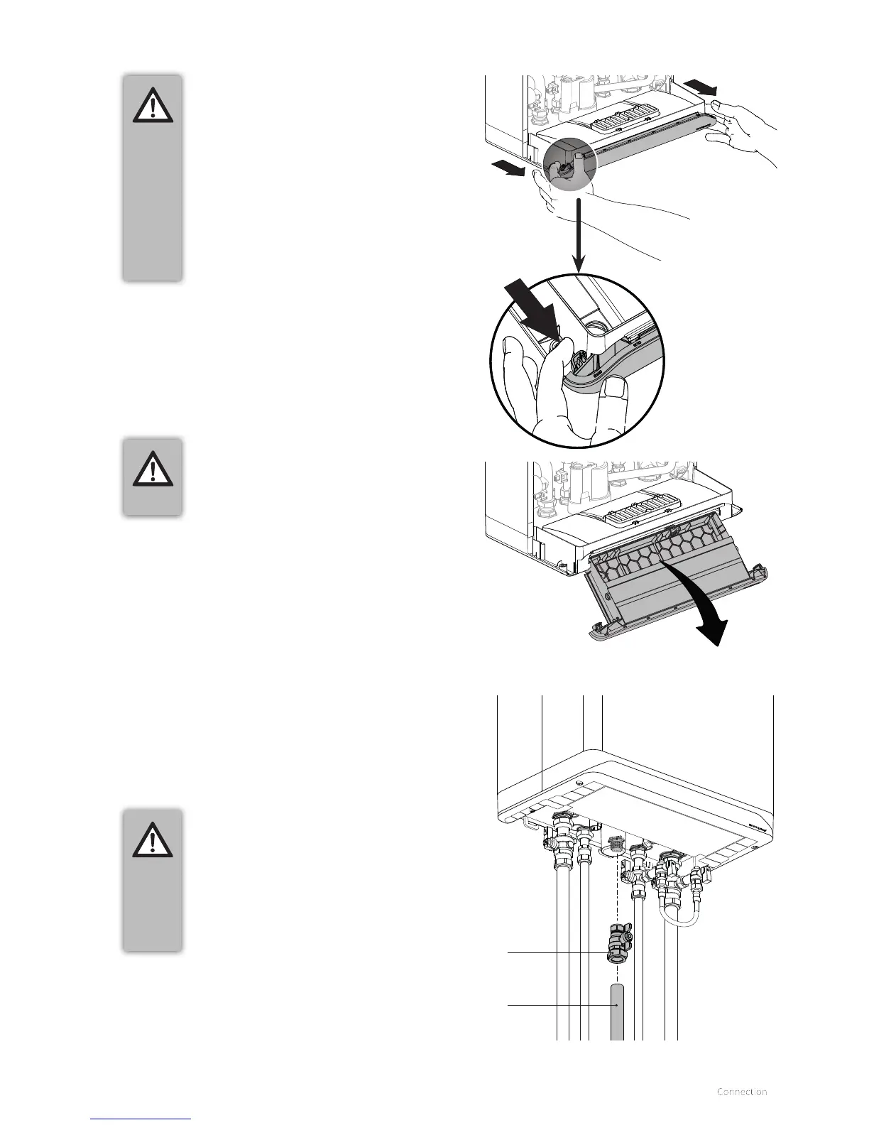
► Fit the gas pipe into the gas valve and tighten this
thoroughly.
► Make sure that the gas pipe is fixed to a rigid surface.
► Open the main gas valve and purge the system.
► Check all connections for leakage.
CAREFUL
► Before starting the work, close the main
gas valve.
► The boiler is intended exclusively to be
installed on a gas supply with a meter
with gas pressure regulator.
► When pollution in the gas is to be
expected a gas filter has to be placed in
the gas pipe to the boiler.
6.4 Gas connection
Gas valve
Main gas
piping
Gas valve
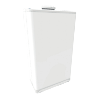
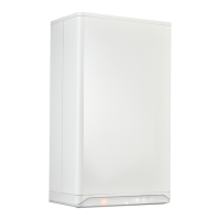
If maintenance activities to the electric circuit must be
performed:
► Remove the front panel (see §5.2.2) and pull the burner
controller unit forward; the burner controller will then tilt
downwards.
► Consult the electrical schematic in §11.1 for making the
connections.
► Aer the desired connections have been made, slide the
burner controller back in the boiler (until the le and right
safeties are again locked) and replace the front panel on the
boiler; see §5.2.2.
► Aer making the desired connections plug the appliance
into an earthed wall socket
CAREFUL
► A fused spur or an unswitched socket
must be located no more than 1 metre
from the appliance.
► For installation in damp rooms a fixed
connection is obligatory.
► When working on the electrical circuit
always isolate the electric supply.
► When the power mains cord must be
replaced, this must be ordered from
Intergas.
CAREFUL
► The Xtreme complies with IPX4D. To
ensure this, cable grommets should
be used when making electrical
connections.