73
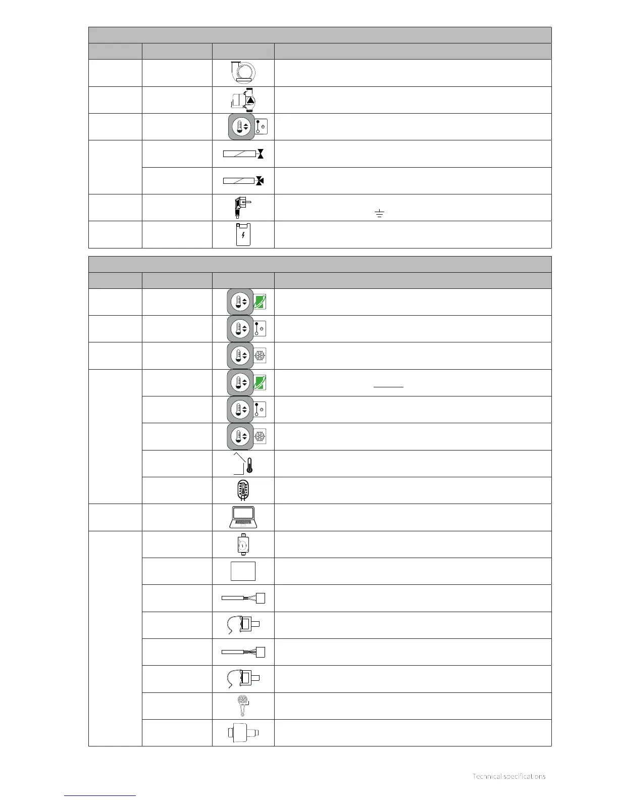
230V~ component
Connector Connections Designation Description
X1
1 – 2 – 3 – 4 –
5 – 6
Fan
X2 1 – 2 – 3
Central heating pump
X3 1 – 2
On
O
On/o room thermostat 230V
X4
1 – 2 – 3
Shut-o valve underfloor heating or groups adjustment
(1=N (blue), 2=L (brown), 3=T (black))
1 – 2 – 3
Three-way valve
(1=N (blue), 2=L (brown), 3=T (black))
X5 1 – 2
Power mains cord 230V~ 50Hz
(1=L (brown), 2=N (blue), = ground (green/yellow))
X8 1 – 2 – 3 – 4 – 5
3
Ignition unit
24V = component
Connector Connections Designation Description
X12 1 – 2
OpenTherm thermostat
X12 1 – 2
Aan
Uit
On/o room thermostat
X12 1 – 2
Frost thermostat if OT thermostat on X13
X13
1 – 2
OpenTherm thermostat (primary connection)
1 – 2
Aan
Uit
On/o room thermostat
1 – 2
Frost thermostat
3 – 4
Outdoor sensor S6 (12k / 25°C)
4 – 5
Boiler sensor S7
X14
PC Interface
X15
1 – 2
Gas valve
3 – 4 – 5 – 6
BMM
BMM (Boiler Memory Module)
7 – 11
Flue gas sensor S5
7 – 16
Domestic hot water sensor S3
7 – 10 – 13
Heat exchanger sensor S0
7 – 15
Central heating flow sensor S1
7 – 9– 17
Flow sensor
7 – 8– 17
Central heating pressure sensor