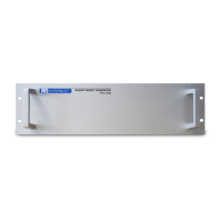
Radar Target Generator - RTG1002 Edition Date: 19-Apr-18
1.3.2. Connectors
• J1 – Rf Input Rx : +10dBm ..-30dBm , 1001MHz .. 3450MHz
• J2 – Rf Input Monitor : output for monitor purposes = Rx input - 8dB
• J3 – Digital Delay Out: delayed signal, unequalized
• J4 – Modulator 2 In : maximum input level +10dBm, +30dBm no damage
• J5 – Modulator 2 Out :equalized output vs freq. maximum output level 0dBm
• J6 – Rf Output Tx : equalized output vs freq. maximum output level 0dBm
• J7 – Generator Out : output of white noise generator, -10 dBm maximum integrated output power
• J8 – RASS : Rass – bus, interface for encoder signals, trigger out and Gate output.
• J9 – RASS : Rass – bus, the same bus interface for encoder signals, trigger out and Gate output
• J10 – GPS : DB9 connector for NMEA-protocol like Intersofts' compact weatherproof GPS, P619
• J11 – SERIAL : serial output ICARUS or towertrack, motor control.
• J12 – ETHERNET : connection to control the RTG1002 hardware.
• J13 – Network 1 : local embedded PC network connection equivalent to J14
• J14 – Network 2 : local embedded PC network connection equivalent to J13
• J15 – DVI: Digital Video Interface, display output
• J16 – USB2.0 : USB connection for keyboard and mouse.
2. REMOTE TEST TARGET
2.1. Theory
For Remote Test Target (RTT) usage the RTG1002 is deployed in the field, typically connected to two small
horns or Log Periodic Antennas positioned on a pole or tripods with a limited height. This way, the radar
antenna system becomes part of the test. The area where a target can be simulated is limited to the azimuth
of choice and a range further than the chosen position. The simulated target can be moving radial or be
fixed.
The fixed target can appear as point clutter (no Doppler) or can have a simulated Doppler frequency.
2.2. Software
Warning: Before you start making connections, estimate/calculate the distance of the set-
up. Whenever you are close to the radar (<200m) add some attenuation to Tx and Rx plug
before you make the setup. The maximum power level at the input should not exceed
+10dBm and the power level at the output should not exceed +20dBm.
1. Load the RTG1002 PSR Target Generation software from the Scenario Generation button in
the PSR Generation section of the RASS-S toolbox.
2. Make sure the network cable is connected between J12 and J13 or J14. Click the little white arrow in
the top left corner to run the vi.
IE-UM-00601-005 RTG1002 User Manual.odt 13/48