Radar Target Generator - RTG1002 Edition Date: 19-Apr-18
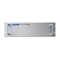
In the example of the previous figure attenuator A consists of 3 separate components. 2 attenuators of 30dB
and 1 attenuator of 20dB, the total amount would 80dB.
The loss of a cable depends on the frequency, for example 0.1dB/(m *GHz). If you have 10meter of cable the
loss would be 1dB at 1 GHz and 3dB at 3GHz.
You can enter a frequency table with multiple points, with a precision of 3.7MHz. The software will interpolate
the values in between data points, but it will not extrapolate.
In the example of the cable if it is described with only two points at 1 and 3GHz, the values inside the interval
will be interpolated but the loss at 3.3GHz will be considered the same as at 3GHz. So it is necessary to
describe the losses up to the minimum and maximum frequency of operation.
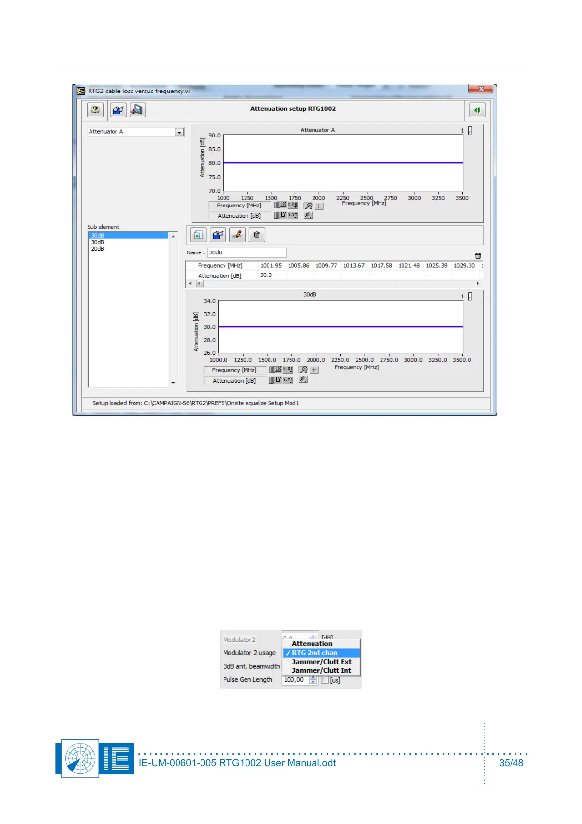
Modulator 2 can be used as a software controlled, fixed(vs azimuth) step attenuator.
It can be used to simulate the high coverage beam, select a VPD and setting 'RTG2nd chan' for the usage of
modulator 2.
IE-UM-00601-005 RTG1002 User Manual.odt 35/48