Radar Target Generator - RTG1002 Edition Date: 19-Apr-18
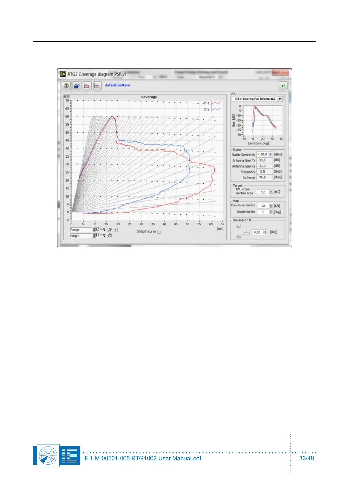
10. The radar coverage diagram will be displayed for the selected or the default VPD. Enter the correct
Radar sensitivity, MDS level (after pulse compression and MTD).
11. Sometimes you may need a constant power for a moving target, for this purpose there is a
theoretical perfect cosecant square VPD available. The corresponding coverage diagram is therefore
flat.
IE-UM-00601-005 RTG1002 User Manual.odt 33/48