Radar Target Generator - RTG1002 Edition Date: 19-Apr-18
data streams to the two users, so half of the received pulses could be missing. There could be gaps
visible in the shape of the received beam.
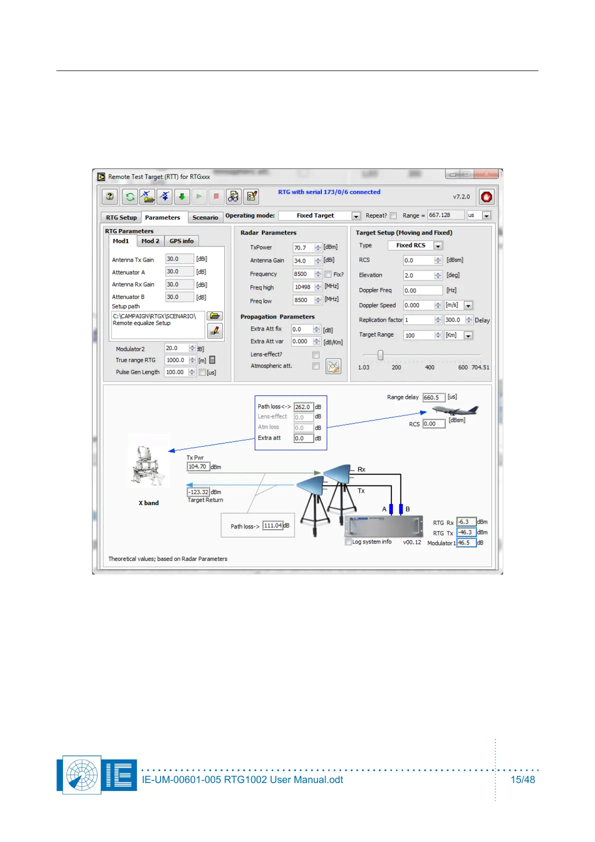
2.2.1. Parameters tab
These parameters must be downloaded into the hardware before they can have an effect.
2.2.1.1. Radar parameters
Tx power: peak power of radar transmitter (subtract cable loss towards the radar antenna)
Antenna gain : Gain of radar Tx antenna, expressed in dBi (do not subtract the cable loss again)
Frequency : This frequency is used in the didactical panel to simulate the radar equation, for the test target.
This frequency will be used to display the correct levels for the trigger in the RTG setup software tab. This
frequency will be used for the power detector when the pulse data is displayed in scope mode (when the
frequency is not yet measured).
IE-UM-00601-005 RTG1002 User Manual.odt 15/48