Radar Target Generator - RTG1002 Edition Date: 19-Apr-18
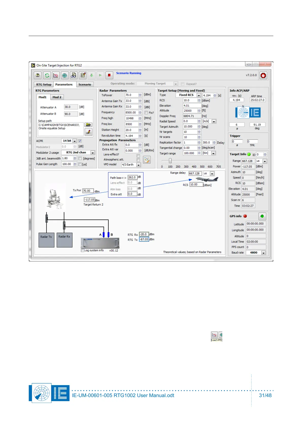
3.3. Parameters Tab
3. Enter parameters of the radar, Tx power antenna gain of Tx antenna and Rx antenna.
4. The horizontal 3dB beam width of the radar antenna must be entered in section of RTG parameters.
A typical value is 1.4degree for most ATC radar.
5. Next to the 3dB ant. beamwidth parameter is a checkbox 'flat beam enable'. When this checkbox is
selected the horizontal beam modulation is disabled and the target will be generated over the 3dB
beamwidth with the power level, calculated for the middle of the beam. You can use this function
when you want to inject a ring with constant power level at a certain delay, when testing the receiver
for example. In this case, increase the 3dB beamwidth to 360/number of targets.
6. Load a VPD file for the simulation, click on the third button in the toolbar.
IE-UM-00601-005 RTG1002 User Manual.odt 31/48