3 6
SECTION 5—REAR WHEELS/FRONT CASTERS
Removing/Installing/Repositioning the Caster
Assemblies
NOTE: If replacing a front caster note the mounting position of the existing front
caster for installation of the new front caster.
NOTE: If repositioning front casters or replacing the existing front caster with a caster
of a different size, refer to Changing Front Seat-to-Floor Height paragraph to determine
the front caster position needed for the required front seat-to-floor height.
NOTE: Both front casters MUST be the same size and adjusted to the same height.
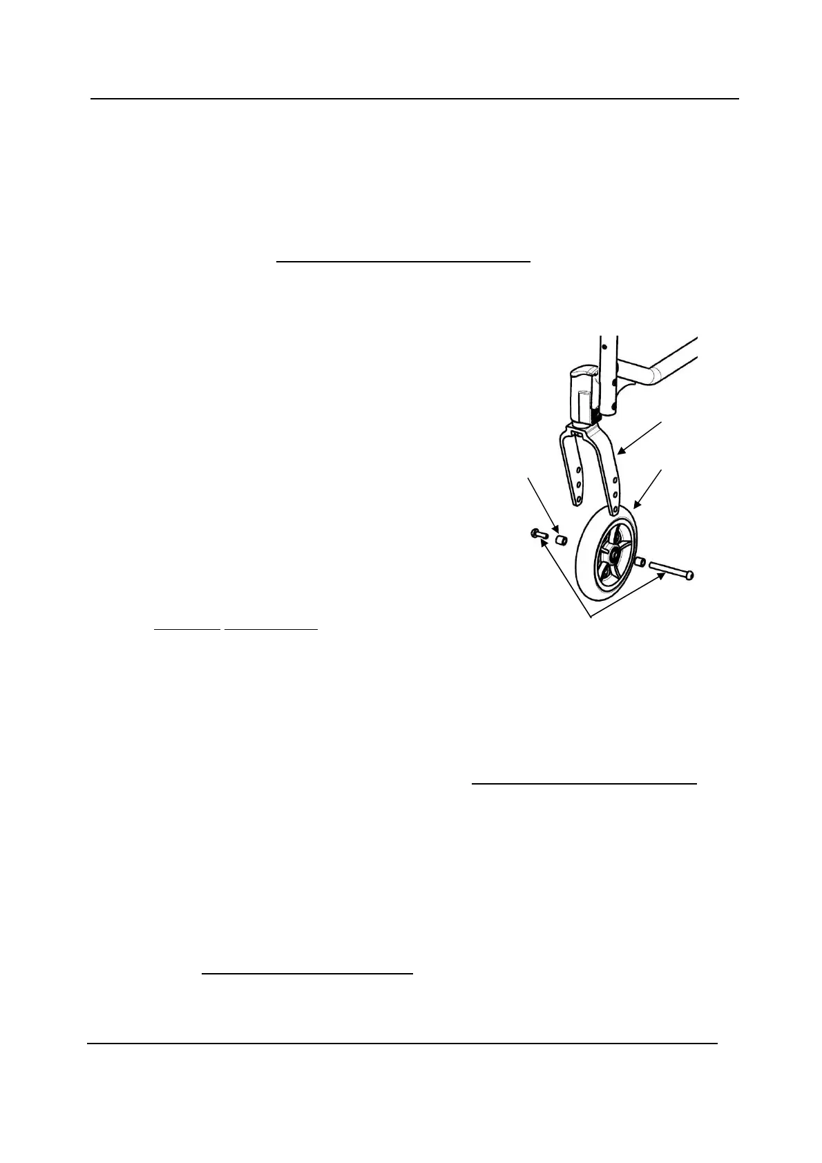
NOTE: For this procedure, refer to FIGURE 5.9.
Removing Front Wheel
1. Remove the mounting bolt (5 mm Allen key), axle
spacers (if present) that secure the front wheel to the fork.
2. Remove the wheel from the fork.
Installing Front Wheel
1. Using the mounting bolt (5 mm Allen key),
axle spacers (if present), secure the wheel to the
desired wheel mounting position.
2. Ensure fork stem is perpendicular to the flat surface.
Refer to Adjusting Caster Angle paragraph.
Adjusting Caster Angle
NOTE: For this procedure, refer to FIGURE 5.10, next page.
1. Remove the two mounting bolts (5 mm Allen key) that secure the caster head tube
assembly to the wheelchair frame.
NOTE: To adjust the caster angle on both sides, use 4 new mounting pre-glued bolts
(M6).
2. Slide down the angle plates set (upper plate and lower plate) from the caster
head tube.
3. Adjust the angle plates set to the desired angle by setting the lower plate as
shown on Detail “A”.
4. Insert the angle plates set into the caster head tube.
NOTE: Both casters head tube should be set at the same angle.
5. Tighten the new mounting pre-glued bolts (13/14 Nm) that secure the caster
head tube assembly to the wheelchair frame
Wheel
Axle Spacers
(if present)
Mounting Bolt
Fork
Caster Assembly
 Loading...