3 7
SECTION 9—REAR WHEELS/FRONT CASTERS
A
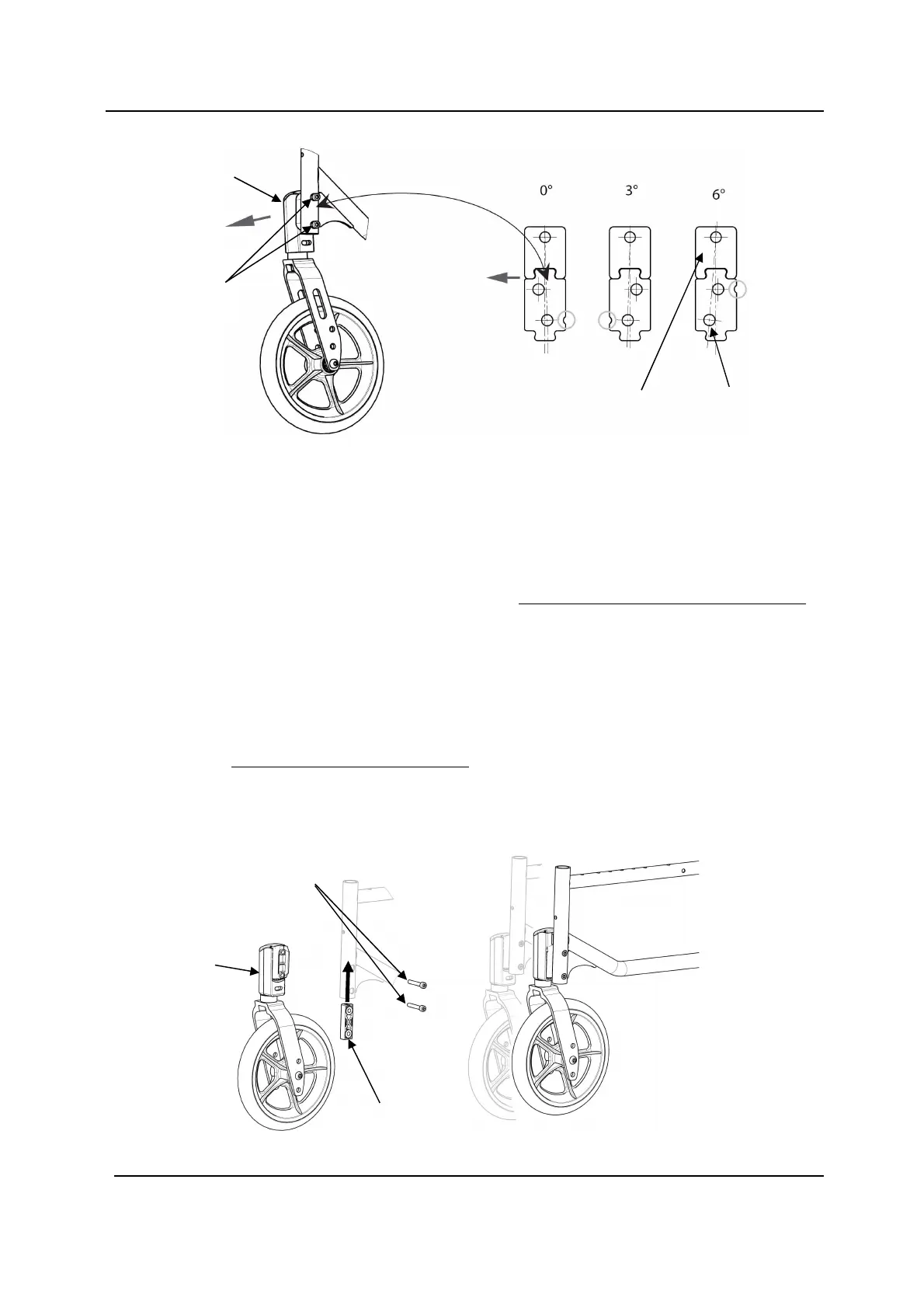
djusting Caster Assembly Position
NOTE: For this procedure, refer to FIGURE 5.11.
1. Remove the two mounting bolts that secure the caster head tube assembly to
wheelchair frame.
NOTE: To adjust the caster position on both sides, use 4 new mounting pre-glued bolts
(M6).
2. Move the caster head tube assembly to one of two positions. Refer to Detail “A” of
FIGURE 5.11. Always check that the plastic insert is present before tightening the
mounting screws.
NOTE: Both caster head tube assemblies should be set at the same position.
3. Tighten the new mounting pre-glued bolts (13/14 Nm) that secure the caster head
tube assembly to the wheelchair frame.
4. Repeat STEPS 1 to 3 for the other caster head tube assembly.
Caster
Head Tube
RH
Upper Plate
Mounting
pre-glued
Bolts
Adjusting Caster Assembly Position
Adjusting Caster Angle
DETAIL «A»
Front RH
Lower Plate
Position P1
Position P2
Caster
Head Tube
RH
Mounting
pre-glued
Bolts
Plastic insert
 Loading...