Version 3.00 | Optidrive P2 User Guide | 57www.invertekdrives.com
8.4.2. Parameter Group 7 – Motor Control
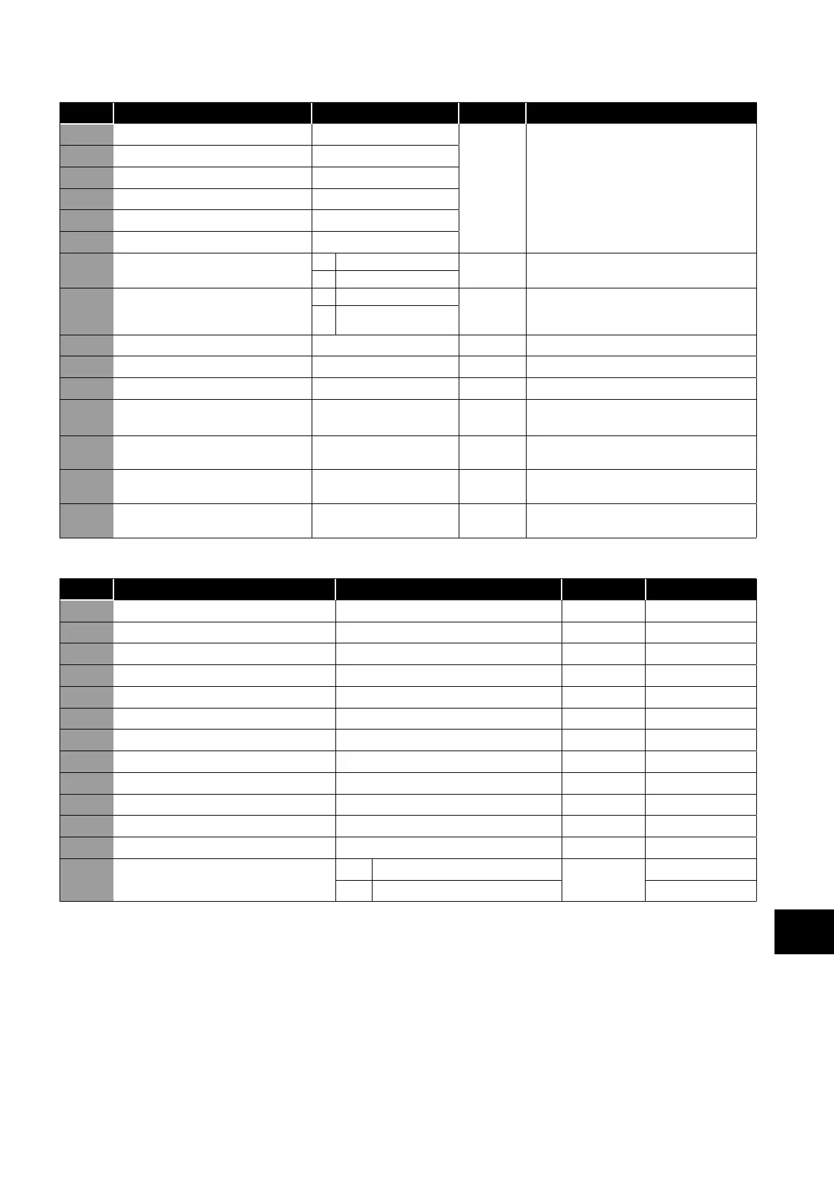
Par. Function Setting Range Default Notes
P7-01 MeasuredMotor Stator Resistance
0.000 – 65.535
Drive
Dependent
Motor date, measured or calculated curing
the autotune.
P7-04 is not used for PM & BLDC Motors.
P7-06 is used only for PM motors.
P7-02 Motor Rotor Resistance
0.000 – 65.535
P7-03 Motor Stator Inductance
0.0000 – 1.0000
P7-04 Motor Magnetising Current
Drive Dependent
P7-05 Motor Leakage Coefficient (Sigma)
0.000 – 0.250
P7-06 Motor Q Axis Inuctance (Lsq)
0.0000 – 1.0000
P7-07 Enhanced Generator Mode
0 Disable
0 Improves motor control in applications with
high regenerative power requirement.
1 Enable
P7-08 Motor Parameter Adaptation
0 Disabled
0 Enables motor parameter adaptation,
intended to compensate for changes in the
motor temperature during operation.
1 Enable
P7-09 Over Voltage Current Limit 0.0 – 100.0% 5.0%
P7-10 System Inertia Constant 0 - 600 10
P7-11 Pulse Width Minimum Limit 0 - 500
P7-12 Magnetising Period 0 – 5000ms Drive
Dependent
Sets the motor magnetising period in V/F Mode.
Sets the motor alignment time in PM modes.
P7-13 Vector Mode Derivative 0.00 – 1.00 0.00 Derivative speed loop gain applied in Vector
control modes.
P7-14 Low Frequency Torque Boost Current 0.0 – 100.0% 0.0% For PM Motors, applies a torque boost current
at low frequency, % x P1-08.
P7-15 Low Frequency Torque Boost Frequency
Limit
0.0 – 50.0% 0.0% For PM motors, determines the frequency, % x
P1-09 when the boost current is removed.
8.4.3. Parameter Group 8 – Additional Ramps and Functions
Par. Function Setting Range Default Notes
P8-01 Acceleration Ramp 2
0.00 – 600.0 / 0.0 – 6000.0s
5.0s
P8-02 Speed Boundary Ramp 1 → Ramp 2
0.0 – P1-01 Hz / Rpm
0.0
P8-03 Acceleration Ramp 3
0.00 – 600.0 / 0.0 – 6000.0s
5.0s
P8-04 Speed Boundary Ramp 2 → Ramp 3
0.0 – P1-01 Hz / Rpm
0.0
P8-05 Acceleration Ramp 4
0.00 – 600.0 / 0.0 – 6000.0s
5.0s
P8-06 Speed Boundary Ramp 3 → Ramp 4
0.0 – P1-01 Hz / Rpm
0.0
P8-07 Deceleration Ramp 4
0.00 – 600.0 / 0.0 – 6000.0s
5.0s
P8-08 Speed Boundary Ramp 4 → Ramp 3 0.0 – P1-01 Hz / Rpm 0.0
P8-09 Deceleration Ramp 3 0.00 – 600.0 / 0.0 – 6000.0s 5.0s
P8-10 Speed Boundary Ramp 3 → Ramp 2 0.0 – P1-01 Hz / Rpm 0.0
P8-11 Deceleration Ramp 2 0.00 – 600.0 / 0.0 – 6000.0s 5.0s
P8-12 Speed Boundary Ramp 2 → Ramp 1 0.0 – P1-01 Hz / Rpm 0.0
P8-13 Ramp Select Control
0 Digital Inputs
0
1 Speed Dependent
8
Extended Parameters
 Loading...

